Electric imaging calibration well group

An electrical imaging and calibration technology, which is applied in the direction of boreholes/well components, earthwork drilling, etc., can solve the problems of weak backflow on the inner wall of the rock module, low imaging accuracy of electrical imaging logging tools, etc., and achieve the effect of improving imaging accuracy

Inactive Publication Date: 2015-07-08
CHINA NAT OFFSHORE OIL CORP +1
View PDF5 Cites 7 Cited by
  • Summary
  • Abstract
  • Description
  • Claims
  • Application Information

AI Technical Summary

Problems solved by technology

[0005] In the existing acoustoelectric imaging calibration well group, images are engraved on the inner wall of the rock module, and the electrical imaging logging instrument i

Method used


Image

  • Electric imaging calibration well group
  • Electric imaging calibration well group

Examples


Example Embodiment

[0026] In order to facilitate the understanding of those skilled in the art, the present invention will be further described below with reference to the accompanying drawings, which shall not be used to limit the protection scope of the present invention.

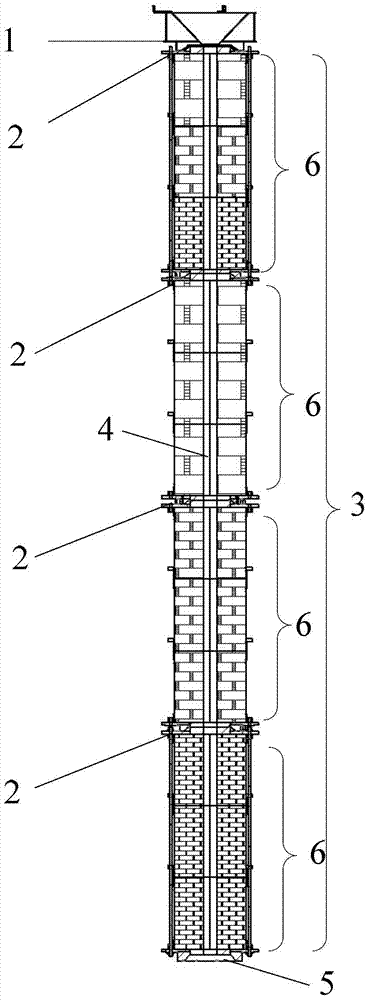
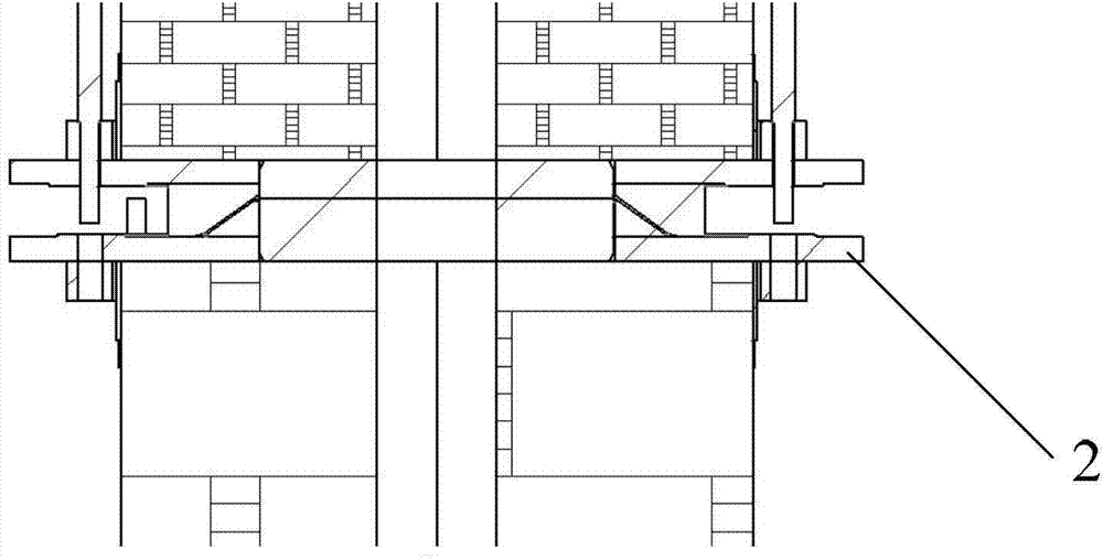
[0027] see figure 1 , the present invention proposes an electro-imaging calibration well group, including at least:

[0028] One or more calibration wells used for inspection and calibration of electrical imaging logging tools.

[0029] Wherein, the calibration well at least includes: a rock module 3, an instrument via hole 4 arranged in the middle of the rock module 3, and a radial slit behind the image of the inner wall of the rock module 3.

[0030] Wherein, the radial gap can be realized by using an openwork technique, and the specific realization belongs to the common knowledge of those skilled in the art, and is not used to limit the protection scope of the present invention, and will not be repeated here.

[0031] ...


PUM


Abstract

The invention discloses an electric imaging calibration well group which at least comprises one or more than one calibration well for verifying and scaling an electric imaging logging instrument, wherein the calibration well at least comprises a rock module (3), and an instrument through hole (4) formed in middle of the rock module (3); a radial gap is included behind the inner wall image of the rock module (3). The radial gap behind the inner wall image of the rock module is used for ensuring backflow of a measurement signal. Thus the imaging precision to the image of the electric imaging logging instrument is improved.

Description

technical field [0001] The invention relates to a borehole electrical imaging well logging technology, in particular to an electrical imaging graduated well group. Background technique [0002] Borehole electrical imaging logging technology refers to the use of sensor array measurement or rotary scanning measurement downhole to collect a large amount of formation information along the longitudinal, circumferential or radial directions of the borehole, and after transmission to the surface, the image processing technology of the borehole wall or well circumference is obtained. Two-dimensional images or three-dimensional images within a certain detection depth around the borehole. [0003] The existing electrical imaging calibration well group at least includes: one or more calibration wells used for inspection and calibration of electrical imaging logging instruments; wherein, the borehole diameters of each calibration well are the same. [0004] Wherein, the calibration wel...

Claims


Application Information

Patent Timeline
IPC IPC(8): E21B49/00
Inventor 张志刚卢涛侯洪为李兴年
Owner CHINA NAT OFFSHORE OIL CORP
Why Eureka
Try Eureka