
led ceiling light

A technology for ceiling lamps and ceilings, applied to lighting devices, cooling/heating devices of lighting devices, light sources, etc., to achieve the effects of cost saving, simple replacement, and guaranteed life

Inactive Publication Date: 2017-10-27
FUJIAN YDJ LIGHT
View PDF9 Cites 3 Cited by
  • Summary
  • Abstract
  • Description
  • Claims
  • Application Information

AI Technical Summary

Problems solved by technology

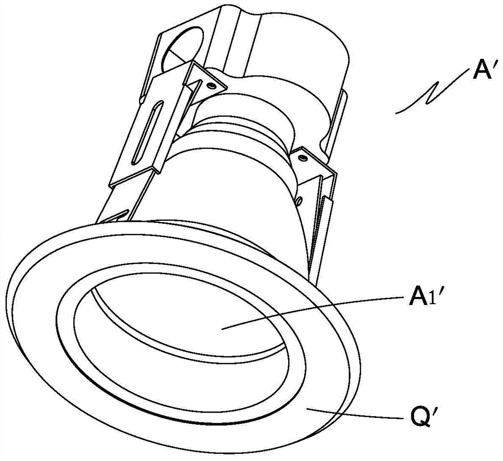
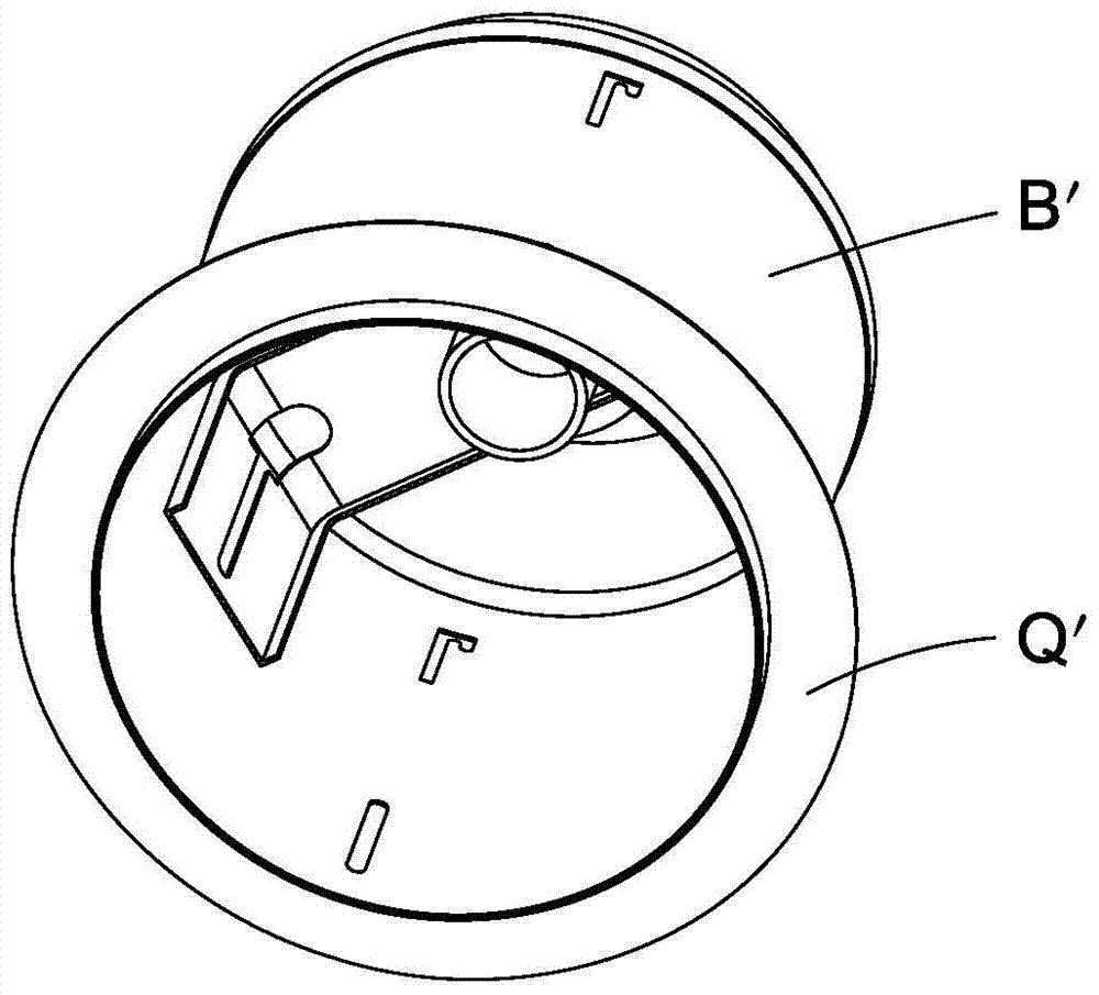
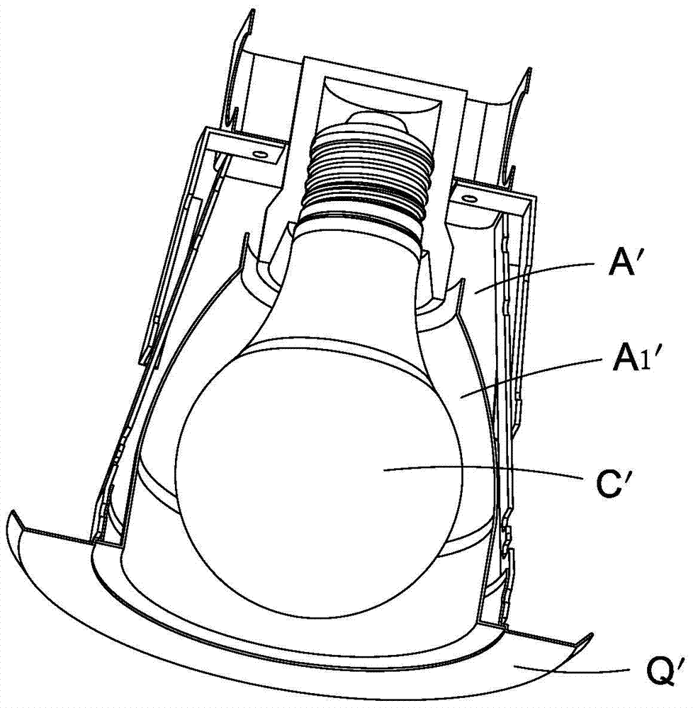
[0009] The technical problem to be solved by the present invention is to provide an LED ceiling light, which solves the defects of the existing LED lighting products to replace the traditional lighting system of the ceiling embedded downlight, and has ideal heat dissipation effect, safe and convenient installation, and good decorative effect

Method used


Image

  • led ceiling light
  • led ceiling light
  • led ceiling light

Examples


Embodiment 1

[0045] Such as Figure 5 to Figure 7bAs shown, this embodiment is an R lamp structure of LED, including a lamp holder 1, a power module 2, a positioning telescopic lamp housing 3, a radiator 4, an LED light-emitting element 5 and a light-transmitting cover 6; the positioning telescopic lamp housing 3 includes a A first housing 31 and a second housing 32 that can be positioned and slid relative to each other along the axis of the lamp head, and can not rotate relative to each other on a plane perpendicular to the axis of the lamp head; the lamp head 1 is connected to the top of the first housing 31, and the power module 2 is located in the positioning telescopic lamp housing 3; the radiator 4 is a hat-shaped structure with a brim 41, the outer surface of the hat top 42 is fixedly connected to the bottom of the second housing 32, and the inner surface of the hat top 41 Connect the LED light-emitting element 5, the brim 41 is adjacent to the corresponding embedded ceiling downlig...

Embodiment 2

[0053] Such as Figure 8 to Figure 8c As shown, this embodiment is a PAR lamp structure of LED, and its difference from Embodiment 1 is that the structure of the light-transmitting cover 6 is different. Glass cover or frosted glass cover, the light-transmitting cover 6 of the PAR lamp structure in Embodiment 2 is a lens. Refer to Embodiment 1 for the rest of the structure, including the radiator 4, the specific structure of the first housing 31 and the second housing 32, and the specific structures such as stepped positioning telescopic, stepless positioning telescopic, etc., all can be the same as Embodiment 1, here I won't repeat them here.


PUM


Abstract

The invention discloses an LED (light-emitting diode) ceiling lamp. The ceiling lamp comprises a lamp holder, a power supply module, a positioning expansion lamp housing, a radiator, an LED light-emitting component and a light transmission cover, wherein the positioning expansion lamp housing comprises a first shell and a second shell, and the first shell and the second shell relatively position and slide in the axial direction of the lamp holder and cannot relatively rotate on the vertical surface of the axis of the lamp holder; the lamp holder is connected with the top of the first shell, the radiator is in a hat-shaped structure with brims, the outer surface of a hat top is fixedly connected with the bottom of the second shell, the inner surface of the hat top is connected with the LED light-emitting component, and the brims are close to a corresponding embedded ceiling down lamp socket; the outer edge of the light transmission cover is connected with the inner surface of the radiator to cover the LED light-emitting component. According to the ceiling lamp, the disadvantage occurred by replacing a traditional illuminating system of an embedded ceiling down lamp with a current LED illuminating product is solved, and thus the ceiling lamp is long in service life, convenient to install and good in decoration effect, and has the significant meaning to energy conservation and environment protection.

Description

technical field [0001] The invention relates to an LED lighting technology, in particular to an LED ceiling lamp. Background technique [0002] Compared with traditional lighting, LED lighting has more energy-saving and higher-quality light performance. It is generally preferred in the new incremental lighting requirements of home, business, and engineering, especially integrated LED lamps: as ceiling embedded lamps, it has The heat dissipation area is large, so that the temperature of the LED chip is low, and the service life is long; the light distribution quality is high, the lighting effect is good; and it has a good decorative effect. [0003] At present, there are a large number of traditional lighting systems for ceiling recessed downlights. The ceiling recessed downlight has a lamp holder connected to various light source lamps, and the structure of the ceiling recessed downlight mainly includes a tube with a reflector cup and a tube without a reflector cup. lamp, ...

Claims


Application Information

Patent Timeline
Patent Type & Authority Patents(China)
IPC IPC(8): F21S8/02F21V29/70F21V17/10F21Y115/10
CPCF21S8/026F21V17/10
Inventor 赖勇清
Owner FUJIAN YDJ LIGHT
Learn More