A 3D energy consumption display method, device and system

A display device, 3D technology, applied in intelligent building energy management, intelligent building field, can solve problems affecting energy management efficiency, limited energy consumption information display, unable to display energy consumption, etc., to achieve the effect of improving energy management efficiency

Active Publication Date: 2018-08-21
BEIJING PERSAGY ENERGY SAVING TECH
View PDF2 Cites 0 Cited by
  • Summary
  • Abstract
  • Description
  • Claims
  • Application Information

AI Technical Summary

Problems solved by technology

[0003] However, the existing BAS system is mainly used for the monitoring of distributed equipment, and distinguishes the spatial distribution of building energy-consuming equipment by naming, and then uses two-dimensional information such as numbers, charts, graphics, and text descriptions to monitor the operation of distributed equipment. The status is displayed, so that the energy consumption monitoring is limited to the display of equipment energy consumption information in two-dimensional space
[0004] When implementing the above energy consumption display method, the inventor found that there are at least the following problems in the prior art: Although the existing BAS system can monitor the energy consumption status of distributed equipment, the two-dimensional display mode makes the energy consumption information display unintuitive , and it is impossible to display the energy consumption according to the distribution of merchants and public areas in the entire floor, so that the property manager cannot timely and accurately understand the energy consumption of each user, so that the property cannot perform energy management from the user dimension, which affects energy management. efficiency

Method used


Image

  • A 3D energy consumption display method, device and system
  • A 3D energy consumption display method, device and system
  • A 3D energy consumption display method, device and system

Examples


Embodiment Construction

[0016] The present invention will be further described in detail below in conjunction with the accompanying drawings and embodiments. It should be understood that the specific embodiments described here are only used to explain the present invention, but not to limit the present invention. In addition, it should be noted that, for the convenience of description, only parts related to the present invention are shown in the drawings but not all content.

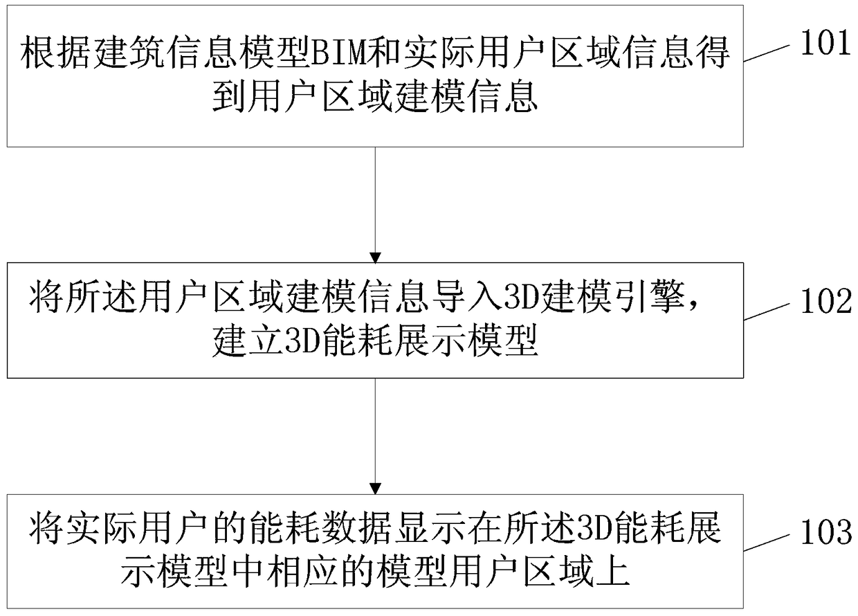
[0017] A specific embodiment of the present invention provides a 3D energy consumption display method, such as figure 1 As shown, the method includes:

[0018] 101. Obtain user area modeling information according to the building information model (BIM) and actual user area information, wherein the actual user area information includes area distribution information of each user and public area in the actual building.

[0019] Among them, Building Information Modeling (Building Information Modeling, referred to as BIM) is based...


PUM


Abstract

The invention discloses a 3D energy consumption display method, a 3D energy consumption display device, and a 3D energy consumption display system, and relates to the field of intelligent buildings. The state of energy consumption of each user area and the public area of each floor can be displayed visually and stereoscopically, so that property managers can monitor energy consumption of buildings from the user dimension, and the energy management efficiency of property management is improved. The method mainly comprises the following steps: obtaining user area modeling information according to building information modeling BIM and actual user area information, wherein the actual user area information includes area distribution information of all users and the public area in an actual building; importing the user area modeling information into a 3D modeling engine and establishing a 3D energy consumption display model; and displaying energy consumption data of an actual user on a corresponding model user area in the 3D energy consumption display model. The 3D energy consumption display method, the 3D energy consumption display device and the 3D energy consumption display system of the invention are mainly used in the process of 3D energy consumption display by user.

Description

technical field [0001] The present invention relates to the field of intelligent buildings, in particular to the field of energy management of intelligent buildings, and in particular to a method, device and system for displaying 3D energy consumption. Background technique [0002] The Energy Management System (EMS for short) adopts a layered distributed system architecture to collect and process the energy consumption data of the building's electricity, gas, water, etc., and analyze the energy consumption of the building, so as to realize the One of the core parts of energy-saving management is the Building Automation System (BAS). BAS can centralize the operating status, safety status, and energy usage status of many scattered electromechanical equipment (such as power transformation and distribution, lighting, elevators, air conditioning, heating, water supply and drainage, fire protection, security, etc.) in buildings or buildings Monitoring, management, and decentraliz...

Claims


Application Information

Patent Timeline
Patent Type & Authority Patents(China)
IPC IPC(8): G06T17/00
Inventor 王鑫王巍徐瑶江江
Owner BEIJING PERSAGY ENERGY SAVING TECH
Why Eureka
Try Eureka