Thermal management system and application method of a gasoline-electric hybrid commercial vehicle
A gasoline-electric hybrid power and management system technology, applied to electric vehicles, circuits, vehicle components, etc., can solve the problems of high equipment cost and poor energy management effect, and achieve low equipment cost, improved utilization rate, and good effect
- Summary
- Abstract
- Description
- Claims
- Application Information
AI Technical Summary
Problems solved by technology
Method used
Image
Examples
Embodiment 1
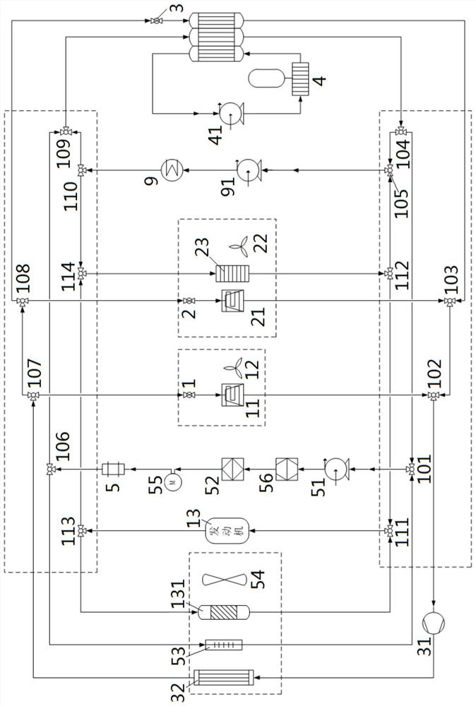
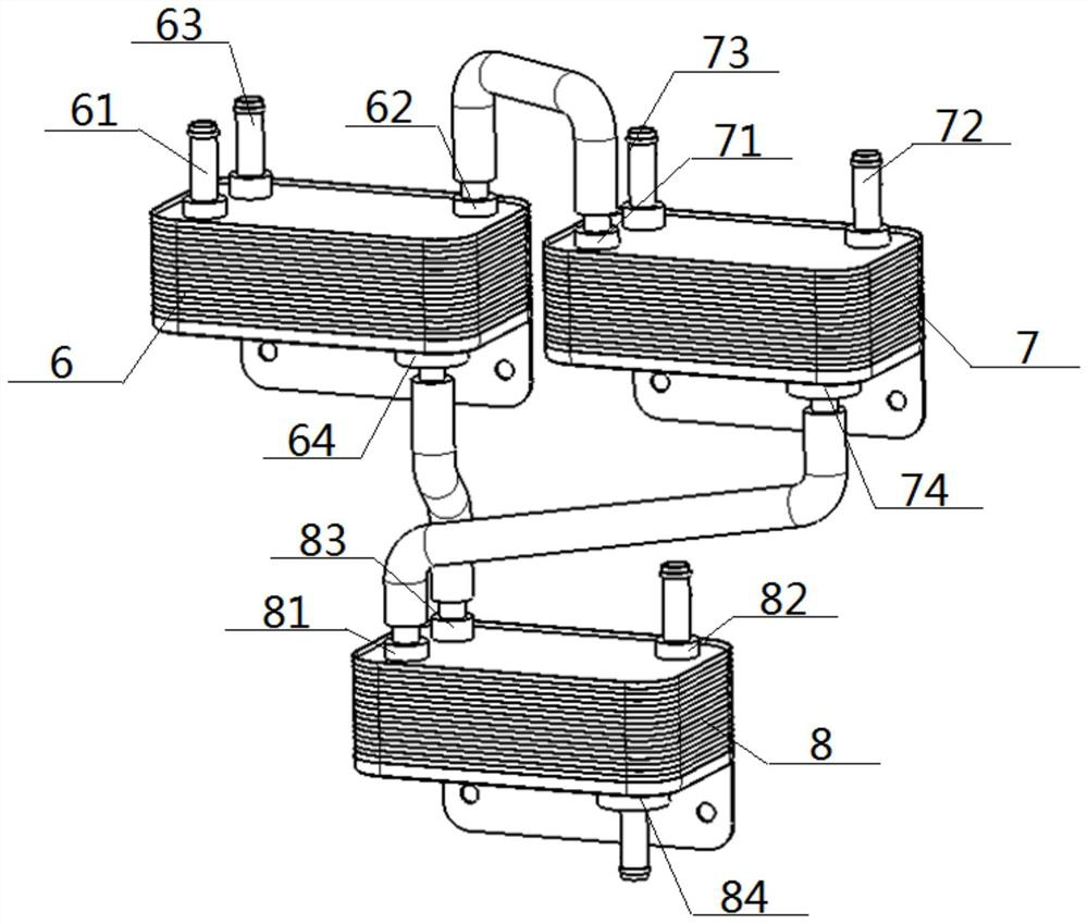
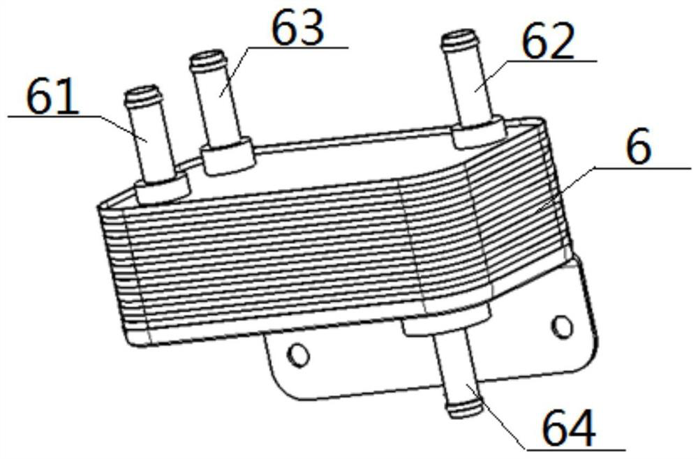
[0068] Hardware structure: see figure 1 — Figure 8, a thermal management system for a gasoline-electric hybrid commercial vehicle, comprising an engine 13, a drive motor 5, an all-in-one controller 52, an ISG generator 55, an ISG controller 56, a power battery 4, a compressor 31, and a motor radiator 53 , condenser 32, first heat exchanger 6, second heat exchanger 7 and third heat exchanger 8; described first heat exchanger 6 comprises first first inlet 61 of intercommunication, first first outlet 62 and first second inlet 63 of intercommunication, First two outlets 64, second heat exchanger 7 includes intercommunicating second one inlet 71, second one outlet 72 and intercommunicating second second inlet 73, second second outlet 74, third heat exchanger 8 includes intercommunicating third one inlet 81, third one outlet 82 With intercommunicating second inlet 83 and second outlet 84, the first outlet 62 communicates with the second inlet 71, the second outlet 74 communicates ...
Embodiment 2
[0074] The hardware structure is the same as that of Embodiment 1, but the method of use is different, and the differences are:
[0075] see figure 2 , image 3 and Figure 4 , the method of use is not the deep cooling process of the battery and the motor in turn, but the battery heating process during the heat engine. Including the following two waterways that are conducted simultaneously:
[0076] B2 outlet 84, water pump 3 41, power battery 4, A2 inlet 63, A2 outlet 64, B2 inlet 83 battery deep cooling waterway; C1 outlet 82, water pump 1 51, ISG controller 56, multiple Integrating controller 52, ISG generator 55, drive motor 5, B2 inlet 73, B2 outlet 74, C1 inlet 81 constitute the motor deep cooling water circuit. In application, the power battery 4 is heated up by the waste heat of the drive motor 5, taking into account the dual requirements of cooling the motor and heating the battery.
[0077] In addition, when the motor needs shallow cooling, there is another met...
Embodiment 3
[0079] On the basis of the hardware structure of Embodiment 1, a water pump 2 91 , a water heater 9 , a warm air core 23 , an evaporator 2 21 , a blower 2 22 and an electronic expansion valve 2 2 are added.
[0080] see Image 6 , the figure is a schematic diagram of the water circuit for battery heating when the machine is cold, and the specific process is: the outlet of water pump 2 91, the water heater 9 (preferably PTC), the inlet of B2 73, the outlet of B2 74, the inlet of C1 81, the outlet of C1 Exit 82, water pump two 91 inlets form water heating and heating waterway; meanwhile, the second battery outlet 84, water pump three 41, power battery 4, first two inlet 63, first second outlet 64, second second inlet 83 battery deep cooling At this time, the water circuit exchanges heat with the water heating water circuit in the heat exchanger to increase the temperature of the power battery 4 .
PUM
 Abstract
Description
Claims
Application Information
 - R&D
- Intellectual Property
- Life Sciences
- Materials
- Tech Scout
- Unparalleled Data Quality
- Higher Quality Content
- 60% Fewer Hallucinations
Browse by: Latest US Patents, China's latest patents, Technical Efficacy Thesaurus, Application Domain, Technology Topic, Popular Technical Reports.
© 2025 PatSnap. All rights reserved.Legal|Privacy policy|Modern Slavery Act Transparency Statement|Sitemap|About US| Contact US: help@patsnap.com


