Oil-electricity hybrid power commercial vehicle heat management system and using method

A technology of hybrid electric power and management system, which is applied in the direction of electric vehicles, circuits, electrical components, etc., can solve the problems of poor energy management effect and high equipment cost, achieve good effect, low equipment cost, and improve market competitiveness

Active Publication Date: 2021-02-12
DONGFENG AUTOMOBILE COMPANY
View PDF6 Cites 0 Cited by
  • Summary
  • Abstract
  • Description
  • Claims
  • Application Information

AI Technical Summary

Problems solved by technology

[0004] The purpose of the present invention is to overcome the defects and problems of poor energy management effect and high equipment cost in the prior art, and provide a thermal management system for hybrid commercial vehicles with better energy management effect and lower equipment cost and how to use

Method used


Image

  • Oil-electricity hybrid power commercial vehicle heat management system and using method
  • Oil-electricity hybrid power commercial vehicle heat management system and using method
  • Oil-electricity hybrid power commercial vehicle heat management system and using method

Examples


Embodiment 1

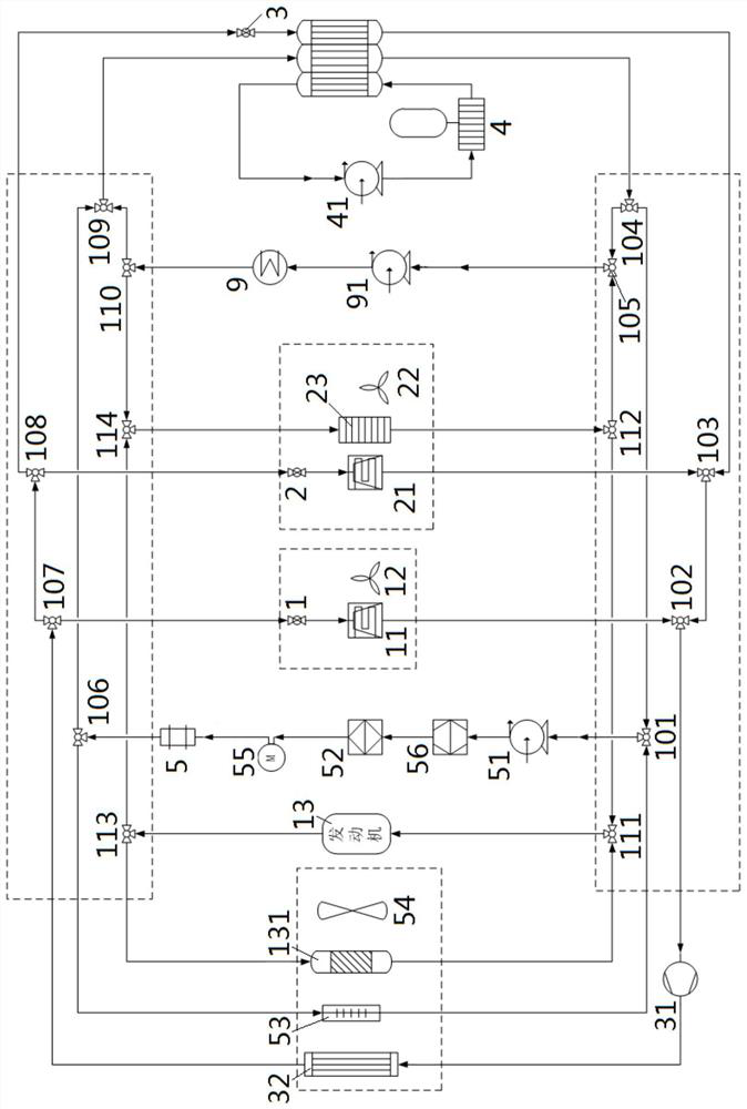
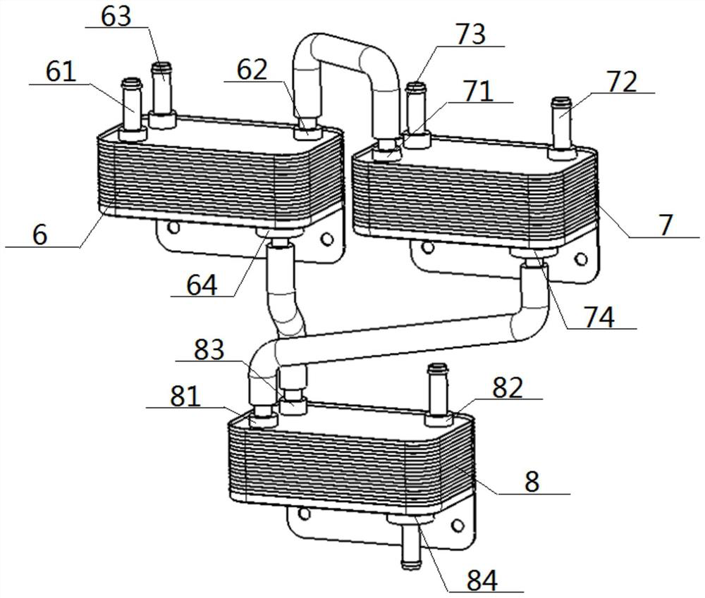
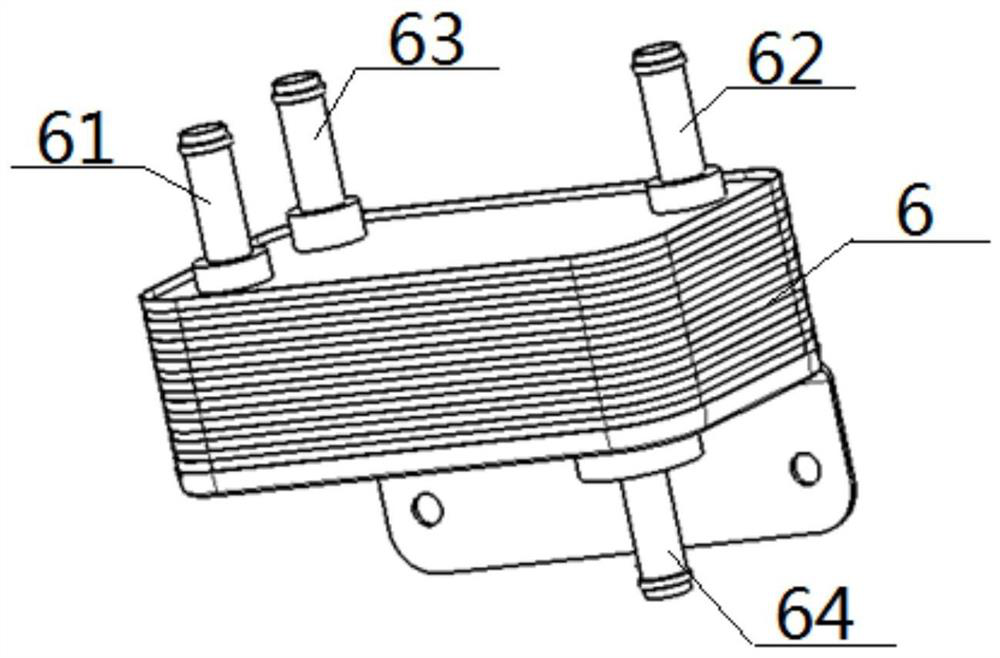
[0068] Hardware structure: see figure 1 — Figure 8, a thermal management system for a gasoline-electric hybrid commercial vehicle, comprising an engine 13, a drive motor 5, an all-in-one controller 52, an ISG generator 55, an ISG controller 56, a power battery 4, a compressor 31, and a motor radiator 53 , condenser 32, first heat exchanger 6, second heat exchanger 7 and third heat exchanger 8; described first heat exchanger 6 comprises first first inlet 61 of intercommunication, first first outlet 62 and first second inlet 63 of intercommunication, First two outlets 64, second heat exchanger 7 includes intercommunicating second one inlet 71, second one outlet 72 and intercommunicating second second inlet 73, second second outlet 74, third heat exchanger 8 includes intercommunicating third one inlet 81, third one outlet 82 With intercommunicating second inlet 83 and second outlet 84, the first outlet 62 communicates with the second inlet 71, the second outlet 74 communicates ...

Embodiment 2

[0074] The hardware structure is the same as that of Embodiment 1, but the method of use is different, and the differences are:

[0075] see figure 2 , image 3 and Figure 4 , the method of use is not the deep cooling process of the battery and the motor in turn, but the battery heating process during the heat engine. Including the following two waterways that are conducted simultaneously:

[0076] B2 outlet 84, water pump 3 41, power battery 4, A2 inlet 63, A2 outlet 64, B2 inlet 83 battery deep cooling waterway; C1 outlet 82, water pump 1 51, ISG controller 56, multiple Integrating controller 52, ISG generator 55, drive motor 5, B2 inlet 73, B2 outlet 74, C1 inlet 81 constitute the motor deep cooling water circuit. In application, the power battery 4 is heated up by the waste heat of the drive motor 5, taking into account the dual requirements of cooling the motor and heating the battery.

[0077] In addition, when the motor needs shallow cooling, there is another met...

Embodiment 3

[0079] On the basis of the hardware structure of Embodiment 1, a water pump 2 91 , a water heater 9 , a warm air core 23 , an evaporator 2 21 , a blower 2 22 and an electronic expansion valve 2 2 are added.

[0080] see Figure 6 , the figure is a schematic diagram of the water circuit for battery heating when the machine is cold, and the specific process is: the outlet of water pump 2 91, the water heater 9 (preferably PTC), the inlet of B2 73, the outlet of B2 74, the inlet of C1 81, the outlet of C1 Exit 82, water pump two 91 inlets form water heating and heating waterway; meanwhile, the second battery outlet 84, water pump three 41, power battery 4, first two inlet 63, first second outlet 64, second second inlet 83 battery deep cooling At this time, the water circuit exchanges heat with the water heating water circuit in the heat exchanger to increase the temperature of the power battery 4 .


PUM


Abstract

The invention relates to an oil-electricity hybrid power commercial vehicle heat management system and a use method. The system mainly comprises an engine, a compressor, a heat exchanger A, a heat exchanger B, a heat exchanger C, a driving motor, an all-in-one controller, an ISG generator, an ISG controller, a refrigerant flowing water path formed by a power battery, a battery deep cooling water path, a motor deep cooling water path, and a motor shallow cooling water path. Any one of a battery and motor sequential deep cooling process, a heat engine battery heating process and a motor shallowcooling process is realized by switching on and switching off various waterways, on the basis, a water pump II and a water heater can be additionally arranged to ensure the heating of the battery during cooling, and a warm air core body, an evaporator II and an air blower II are additionally arranged to realize the heating and cooling of a cab. The temperature rise of the cab has two types according to whether the engine dissipates heat or not so that the energy of the refrigerant and the heat generated by the vehicle are managed. According to the design, an energy management effect is good, the equipment cost is low, a compatible effect is good, and control is easy.

Description

technical field [0001] The invention relates to a thermal management system for a vehicle, which belongs to the technical field of new energy vehicles, and in particular to a thermal management system and a use method of an oil-electric hybrid commercial vehicle. Background technique [0002] At present, the cooling and heating systems of various gasoline-electric hybrid vehicles on the market are independent of each other, such as gasoline-electric hybrid light trucks and gasoline-electric hybrid refrigerated vehicles, which not only leads to unreasonable energy distribution, reduces energy utilization, and makes Each area that needs to be heated or cooled requires a separate heating or cooling system, which increases the cost of the equipment. [0003] The disclosure of information in this background section is only intended to increase the understanding of the general background of this patent application, and should not be considered as an acknowledgment or any form of s...

Claims


Application Information

Patent Timeline
IPC IPC(8): B60H1/00B60H1/03B60L58/26B60L58/27H01M10/613H01M10/615H01M10/625H01M10/6556H01M10/6567H01M10/6568H01M10/663
CPCB60H1/004B60H1/00278B60H1/00271B60H1/034B60L58/26B60L58/27H01M10/613H01M10/615H01M10/625H01M10/6556H01M10/6567H01M10/6568H01M10/663B60H2001/00307Y02E60/10
Inventor 刘中历程林汪斌王为才唐军石秀柱王涛朱金宝
Owner DONGFENG AUTOMOBILE COMPANY
Why Eureka
Try Eureka