Bending high-voltage shielding plug

A shielding plug, high-voltage technology, applied in the direction of coupling devices, electrical components, connections, etc., can solve the problems that cannot meet the requirements of new energy vehicles for the use of curved shielding plugs, the shielding treatment method has poor shielding efficiency, and cannot meet the use requirements, etc. , to achieve the effect of reducing quality and production cost, reliable fixing method and high practical value

Active Publication Date: 2015-07-08
SICHUAN YONGGUI SCI & TECH CO LTD
View PDF5 Cites 4 Cited by
  • Summary
  • Abstract
  • Description
  • Claims
  • Application Information

AI Technical Summary

Problems solved by technology

[0003] The traditional curved outlet electrical connector plug generally adds an elbow at the end of the plug to achieve the purpose of the curved outlet. The elbow and the plug shell are connected by threads or buckles. , only suitable for small current plugs, because high current plugs need to use cables with larger cross-sectional areas, and cables with large cross-sectional areas have a larger turning radius, and the solution of adding a bend at the end of the plug cannot meet the requirements; the traditional For a plug with a large current curved outlet, generally a terminal and a wire connector are used first, and then the terminal is connected to the contact to achieve a curved outlet. Type outlet, but after the shell is made into a component, the protection level is difficult to meet the standard; the traditional angled connector plug with shielding function usually uses a pair of separate contacts to realize the conduction between the shields. This method of shielding treatment The shielding effect of the method is not good, and because of the extra shielded conductive contact pairs, the size of the connector is increased. It can be seen that the traditional bent outlet plug with shielding function cannot meet the requirements of modern industrial electrical systems, especially Requirements for the use of curved shielded plugs for new energy vehicles

Method used


Image

  • Bending high-voltage shielding plug
  • Bending high-voltage shielding plug
  • Bending high-voltage shielding plug

Examples


Embodiment

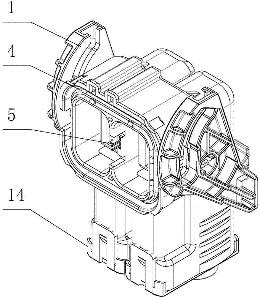
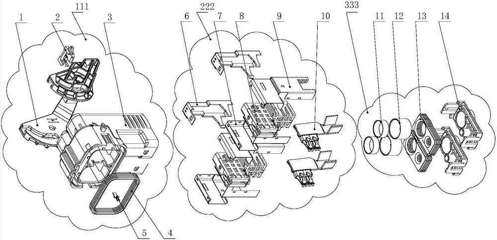
[0036] Such as Figure 1-3 As shown, a curved high-voltage shielded plug is composed of a shell assembly 111 , a contact piece and a mounting plate assembly 222 , and a tail attachment 333 .

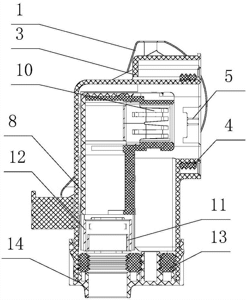
[0037] The shell group 111 is composed of a locking handle 1, a lock block 2, a plug shell 3, a sealing ring 4, and a signal pin 5.

[0038] The contact piece and mounting plate assembly 222 is composed of a rear cover 6 , a left shield 7 , a front mounting plate 8 , a right shield 9 and a contact 10 .

[0039] Tail attachment 333 is made up of shielding pad cover 11 , shielding pressure sleeve 12 , sealing wire body 13 , and tail cap 14 .

[0040] Such as Figure 4 with Figure 5 As shown, the two sides of the plug housing 3 are symmetrically provided with two elliptical rotating shafts 3-1, a fool-proof keyway 3-2 is provided at the insertion joint, and a locking buckle 3-3 is provided on the back of the plug housing 3, and the plug housing 3 The tail is provided with a tail cover ...


PUM


Abstract

The invention discloses a bending high-voltage shielding plug, and relates to the electric connector field of the electric appliance field of new-energy vehicles, industrial equipment, urban rails and railway vehicles. The bending high-voltage shielding plug comprises a shell assembly, a contact piece, an installation plate assembly and a tail accessory. The shell assembly is composed of a locking handle, a locking block, a plug shell, a seal ring and a signal pin. Locking and unlocking of a connector are achieved by adopting a mechanism which can convert handle rotation motion into rectilinear motion of the plug shell relative to a socket shell, the electric connector can be normally used on the condition that the operation space is narrow, the problem that a locking mode of a traditional electric connector cannot be normally used in the narrow operation space is solved, and meanwhile the handle has the power-assistant effect so that the operability of the connector is improved.

Description

technical field [0001] The invention relates to the field of electrical connectors in the electrical fields of new energy vehicles, industrial equipment, urban rail and railway vehicles, in particular to curved high-voltage shielding plugs used in new energy vehicles. Background technique [0002] In modern industrial electrical systems, the use of electrical connectors is becoming wider and wider, and the number is increasing. There are also more and more requirements for the outlet methods of the connectors, and the demand for 90-degree bent outlets is the majority. [0003] The traditional curved outlet electrical connector plug generally adds an elbow at the end of the plug to achieve the purpose of the curved outlet. The elbow and the plug shell are connected by threads or buckles. , only suitable for small current plugs, because high current plugs need to use cables with larger cross-sectional areas, and cables with large cross-sectional areas have a larger turning rad...

Claims


Application Information

Patent Timeline
Patent Type & Authority Applications(China)
IPC IPC(8): H01R13/639H01R13/6581
Inventor 李统刚彭果
Owner SICHUAN YONGGUI SCI & TECH CO LTD
Why Eureka
Try Eureka