Reactive Power Cooperative Compensation System and Compensation Method for Low-Voltage Lines in Distribution Network

A low-voltage line and compensation method technology, applied in reactive power compensation, reactive power adjustment/elimination/compensation, etc., can solve the problems of inability to fully input decentralized compensation, over-compensation of the power grid system, damage to the power grid system, etc., to improve the power factor and power supply quality, reducing line loss and improving safety

Active Publication Date: 2017-03-01
NANNING MICRO CONTROL HIGH TECH
View PDF4 Cites 0 Cited by
  • Summary
  • Abstract
  • Description
  • Claims
  • Application Information

AI Technical Summary

Problems solved by technology

With this scheme, when the terminal line voltage drops, the input capacitor can not only compensate the reactive power of the line, but also increase the terminal line voltage at the same time; however, this scheme has some limitations to the setting of the line voltage target value as the compensation criterion. Otherwise, due to the lack of synergy between centralized compensation and decentralized compensation, in some cases, such as the peak period of power consumption, the centralized compensation is often fully invested and still undercompensated, but the decentralized compensation is due to the line voltage target value setting. In other cases (such as the low power consumption section in the second half of the night, the user's load type / consumption has a large change, or other similar situations) to achieve For the set line voltage target value, the decentralized compensation device may still continue to invest in compensation, which will cause overcompensation to the grid system that is difficult for the centralized compensation device to offset, thus causing damage to the grid system

Method used


Image

  • Reactive Power Cooperative Compensation System and Compensation Method for Low-Voltage Lines in Distribution Network

Examples


Embodiment Construction

[0028] The reactive power cooperative compensation system and compensation method of the distribution network low-voltage line of the present invention will be further described below in conjunction with the accompanying drawings and specific embodiments.

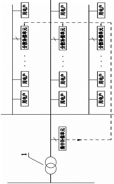
[0029] figure 1 It is a schematic block diagram of the composition principle of an embodiment of the reactive power cooperative compensation system of the present invention. Such as figure 1 As shown, the reactive power cooperative compensation system of the present invention is mainly composed of a centralized compensation unit arranged on the low-voltage side of the distribution transformer 1 in the station area and a decentralized compensation unit arranged in the middle and rear sections of each distribution outlet in the station area; the centralized compensation Both the unit and the distributed compensation unit are compensated based on the existing principle of using parallel capacitors, and respectively include a ...


PUM


Abstract

The invention discloses a reactive power cooperative compensation system and a compensation method for a low-voltage line of a distribution network. By setting up a centralized compensation unit and a decentralized compensation unit and organically combining them, the low-voltage side can be adjusted under the condition that the overall input cost of the system is low. The transmission lines and distribution transformers realize the intelligent collaborative compensation of reactive power. The system and method of the present invention can reduce line losses, and are especially suitable for reactive power compensation of rural power grids and distribution lines using public transformers, which help to improve the power factor of the entire power distribution system, increase the voltage at the end of the power supply line, and improve the reliability of the power grid. Safe, economical and efficient operation level.

Description

technical field [0001] The invention relates to the technical field of reactive power compensation, in particular to a reactive power cooperative compensation system and a compensation method for a low-voltage line of a distribution network. Background technique [0002] In the distribution network, the reactive power generated by the power generator and the power of the transmission line are often insufficient to meet the reactive power demand of a large number of motors, transformers, reactors, fluorescent lamps and other inductive loads in the network and the reactive power loss in the system. , so it is easy to cause the power factor of the grid to drop and the utilization rate of the grid system to decrease. In order to reduce active power loss and voltage drop, reduce loss in power transmission, ensure safe, economical and efficient operation of the power grid, and improve the capacity and quality of power transmission, it is usually necessary to perform nearby reactiv...

Claims


Application Information

Patent Timeline
Patent Type & Authority Patents(China)
IPC IPC(8): H02J3/18
CPCY02E40/30
Inventor 骆武宁
Owner NANNING MICRO CONTROL HIGH TECH
Why Eureka
Try Eureka