Rotor for a permanent magnet electric machine and use thereof

A permanent magnet and rotor technology, applied in the direction of magnetic circuit rotating parts, magnetic circuits, electromechanical devices, etc., can solve the problems of low efficiency, positioning torque and torque consistency, and achieve improved torque consistency, expensive and simple , The effect of small detent torque

Inactive Publication Date: 2015-07-08
CONTINENTAL TEVES AG & CO OHG +1
View PDF3 Cites 5 Cited by
  • Summary
  • Abstract
  • Description
  • Claims
  • Application Information

AI Technical Summary

Problems solved by technology

Furthermore, existing electric motors do not adequately meet the requirements of modern applications in motor vehicles, especially efficiency, low detent torque and torque uniformity

Method used


Image

  • Rotor for a permanent magnet electric machine and use thereof
  • Rotor for a permanent magnet electric machine and use thereof
  • Rotor for a permanent magnet electric machine and use thereof

Examples


Embodiment Construction

[0039] In order to be able to describe the exemplary embodiment concisely, identical elements are provided with the same reference numerals and only details relevant to the invention are explained in each case.

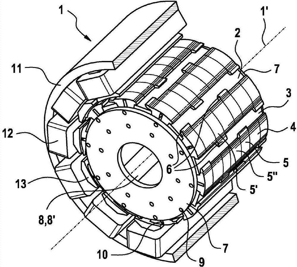
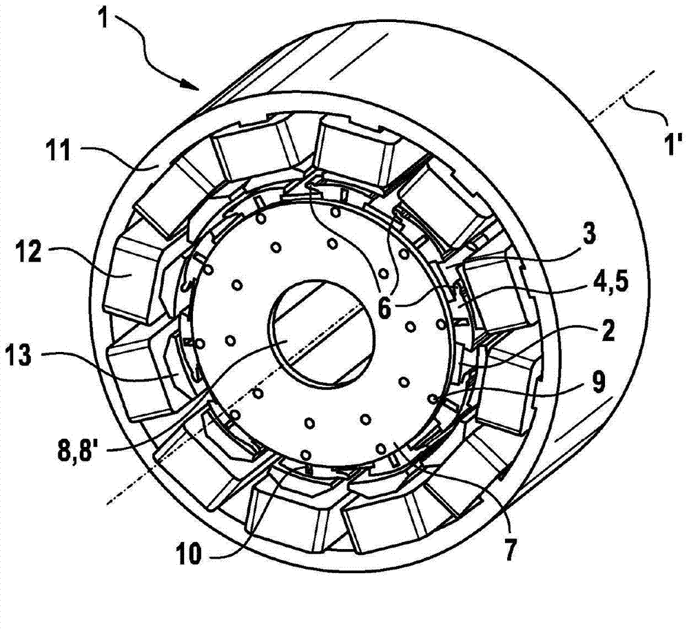
[0040] figure 1 Taking the electric motor 1 as an example, a perspective view of the electric motor 1 according to the invention is shown, limited to the essential components—the stator 11 and the rotor 2 , the stator 11 being drawn in section for illustration. figure 2 The electric motor 1 is likewise shown in a simplified perspective view, but not shown in section.

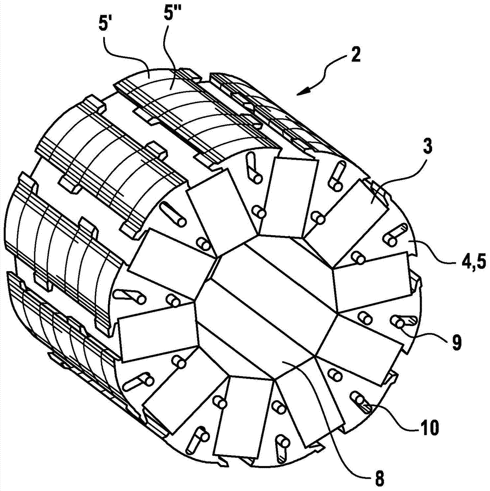
[0041] Field coils 12 are arranged on the pole shoes 13 of the stator 11 around the rotation of the rotor 2 and are electrically excited in a manner known per se to cause a rotation of the rotor by generating a rotating magnetic field. The rotor 2 comprises permanent magnets 3 and pole segments 4 which extend along the rotor axis and are arranged coaxially around the rotor axis 1 ′, alternating circum...


PUM


Abstract

Rotor (2) for a permanent magnet electric machine (1), in particular a brushless DC machine, which rotor is arranged concentrically about a rotor axis (1') and has a passage opening (8) running along the rotor axis (1') for accommodating a shaft (22), comprising permanent magnets (3) and pole segments (4) extending along the rotor axis (1'), wherein the permanent magnets (3) and the pole segments (4) are arranged alternately around the rotor axis (1') in the circumferential direction, which rotor is further distinguished in that a cross-sectional area (14) of at least one, in particular each, pole segment (4) is formed, in at least one first pole segment region (5), asymmetrically with at least one shaped portion (6) arranged in a radially outer region, with respect to the rotor axis (1'), of the pole segment (4), wherein the shaped portion (6) extends substantially in a circumferential direction (1''). Furthermore, the invention describes the use of the rotor according to the invention.

Description

technical field [0001] The invention relates to a rotor for a permanent magnet electric machine according to the preamble of claim 1 and to the use of the rotor. Background technique [0002] Electric machines are, for example, electric motors and generators, which perform different tasks, especially in motor vehicles. [0003] DE 10 2010 061 778 A1 describes a spoked rotor of an electric machine in which permanent magnets are arranged in the form of spokes in the rotor base body, wherein the rotor axis is a virtual intersection point and the permanent magnets are alternately oppositely polarized in the circumferential direction. The magnetic flux is guided to the air gap via pole segments arranged between the permanent magnets in order to achieve a concentration of the magnetic flux. Thus, magnetic south and north poles alternate along the circumference of the rotor. [0004] In order to reduce the leakage flux and increase the efficiency of the machine, DE 10 2010 061 77...

Claims


Application Information

Patent Timeline
Patent Type & Authority Applications(China)
IPC IPC(8): H02K29/03
CPCH02K1/2773H02K29/03H02K2201/06H02K1/28
Inventor P·斯陶德B·皮勒T·考夫曼T·科皮克
Owner CONTINENTAL TEVES AG & CO OHG
Why Eureka
Try Eureka