

Waste heat recovery system of water dispenser
A waste heat recovery system and water dispenser technology, applied in beverage preparation devices, home appliances, applications, etc., can solve the problems of energy waste and low heating efficiency, and achieve the effect of speeding up the water output and increasing the amount of hot water output
- Summary
- Abstract
- Description
- Claims
- Application Information
AI Technical Summary
Problems solved by technology
Method used
Image

Examples
Embodiment Construction
[0018] The present invention will be further described below in conjunction with the accompanying drawings.
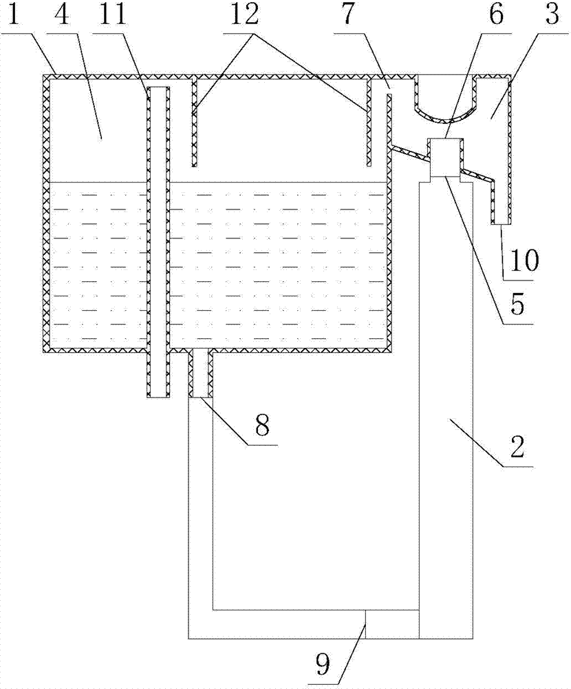
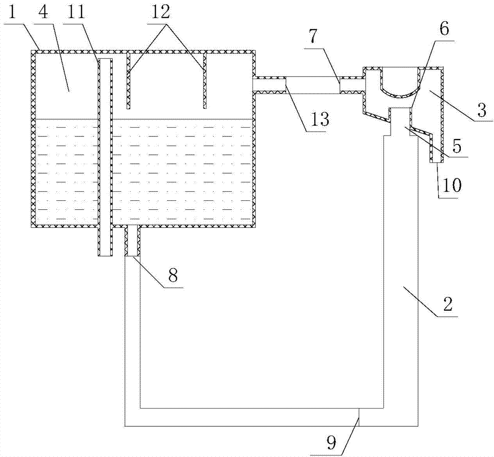
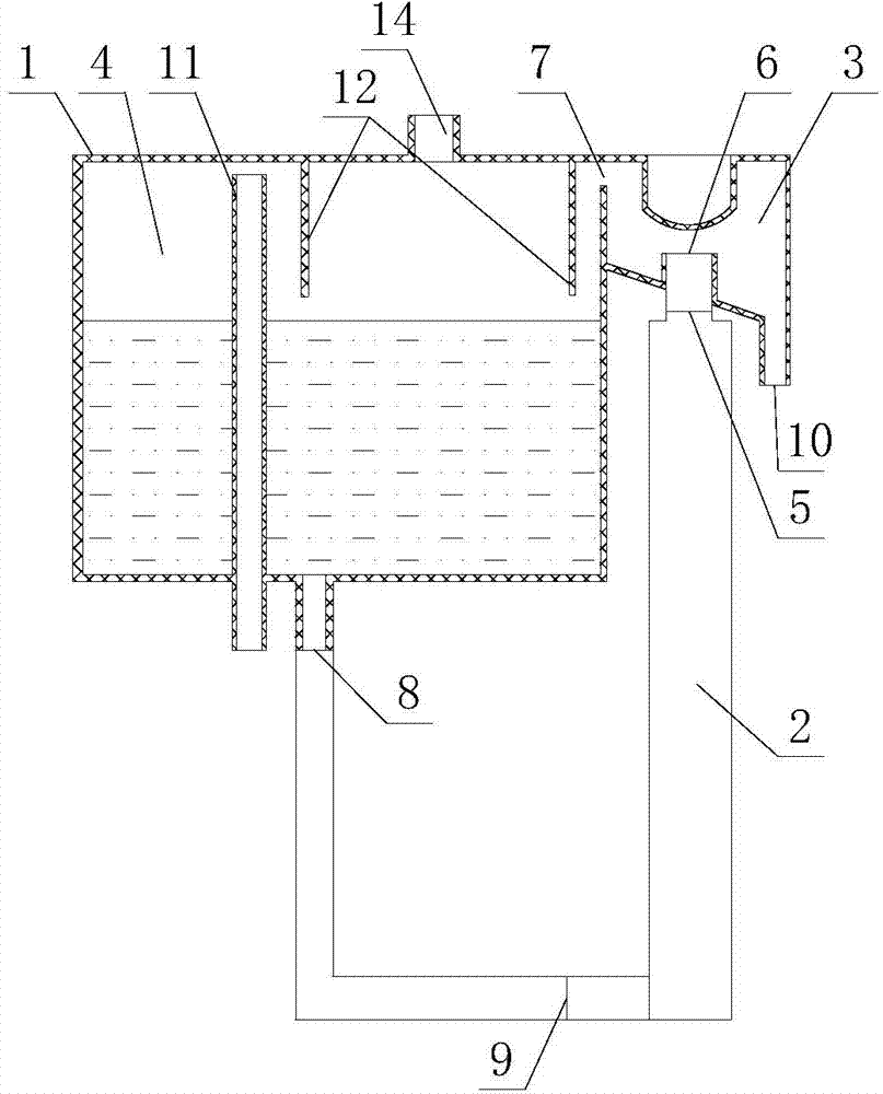
[0019] refer to Figure 1 ~ Figure 3 , a waste heat recovery system for water dispensers, including a water tank 1 and a heating body 2, the water tank 1 includes a water inlet chamber 4 and a water vapor separation chamber 3, the water outlet 8 of the water inlet chamber 4 and the water inlet of the heating body 2 9, the outlet 5 of the heating body 2 is connected to the inlet 6 of the water vapor separation chamber 3, the lower part of the water vapor separation chamber 3 has a hot water outlet 10, and the upper part of the water vapor separation chamber 3 has an exhaust port 7, the steam exhaust port 7 communicates with the steam inlet 13 of the water inlet chamber 2, the position of the steam inlet 13 is higher than the water surface of the water inlet chamber 4, and the water inlet chamber 4 is provided with There is a ventilation tube 11, the inlet of the ventil...
PUM
 Abstract
Description
Claims
Application Information