Metal alternative extrusion forming device and method

An extrusion forming and metal technology, which is applied in the field of labor-saving extrusion forming devices, can solve the problems of poor flow uniformity, low material utilization rate, high energy consumption, etc., and achieve reduction of extrusion load, improvement of material utilization rate, and flow uniformity Improved effect

Active Publication Date: 2015-07-15
福建祥鑫股份有限公司
View PDF6 Cites 7 Cited by
  • Summary
  • Abstract
  • Description
  • Claims
  • Application Information

AI Technical Summary

Problems solved by technology

[0008] The purpose of the present invention is to provide a metal extrusion forming device and method, in order to solve the problems of large energy consumption, poor flow uniformity and low material utilization rate in the current extrusion forming device and method

Method used


Image

  • Metal alternative extrusion forming device and method
  • Metal alternative extrusion forming device and method
  • Metal alternative extrusion forming device and method

Examples


specific Embodiment approach 1

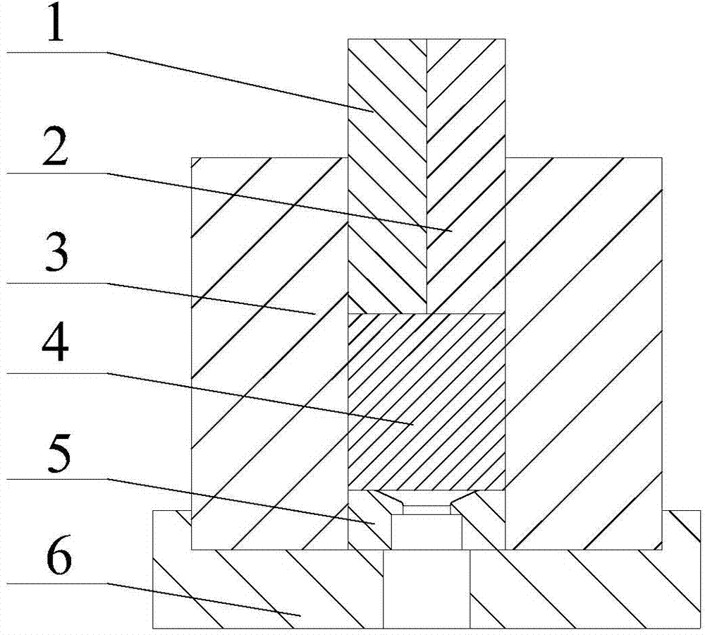
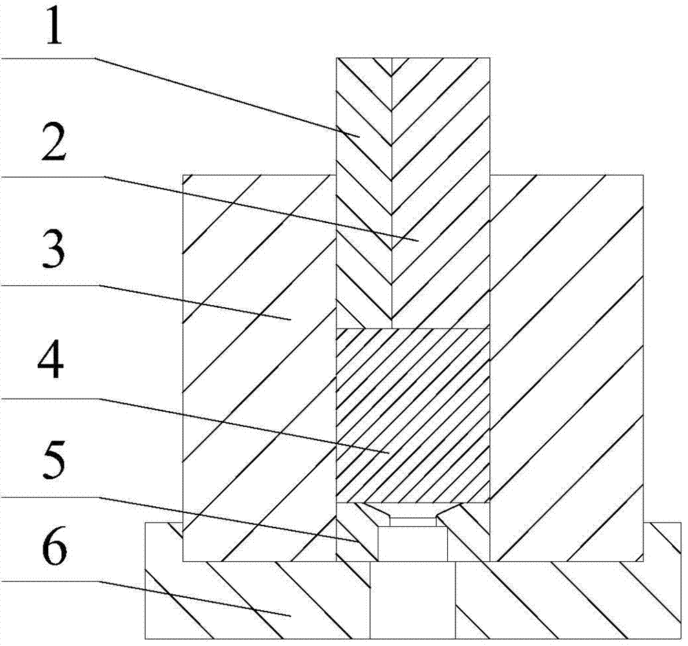
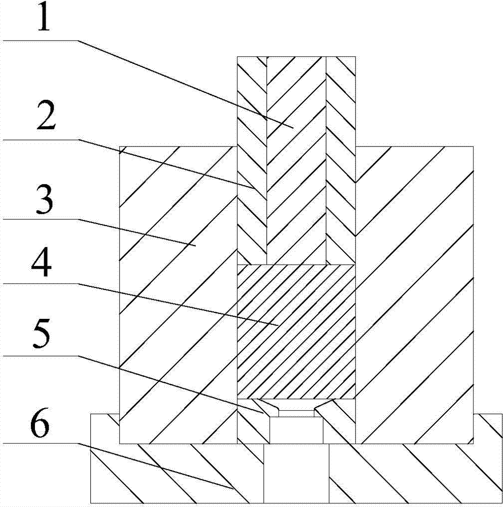
[0021] Specific implementation mode one: combine figure 1 Describe this embodiment, the device of this embodiment comprises first punch 1, second punch 2, extruding cylinder 3, mandrel 5 and base 6, extruding cylinder 3 is arranged on base 6, and mandrel 5 is located at At the bottom of the extrusion barrel 3, the blank 4 is set in the extrusion barrel 3 and above the mandrel 5, and one end of the first punch 1 and the second punch 2 is set in the extrusion barrel 3 and leans against the blank 4 of the upper end.

specific Embodiment approach 2

[0022] Specific implementation mode two: combination figure 1 Describe this embodiment, the first punch 1 and the second punch 2 of this embodiment are arranged side by side, the height of the first punch 1 and the second punch 2 are the same, the horizontal direction of the first punch 1 and the second punch 2 The cross-section is bow-shaped and the two cross-sections form a circle that matches the extrusion cylinder. The punches are arranged on the left and right to facilitate the alternate downward loading of the two punches, which can reduce the forming load during the extrusion process and reduce the shearing at the interface. Deformation promotes the refinement of grain depth and the improvement of mechanical properties, and the benefits of left and right settings are analyzed. Other implementation manners are the same as the specific implementation manner 1.

specific Embodiment approach 3

[0023] Specific implementation mode three: combination figure 1 To describe this embodiment, the cross-sectional ratio of the first punch 1 and the second punch 2 in this embodiment is 1:1, and the load reduction effect is the most significant in this ratio. Other implementation manners are the same as the specific implementation manner 1.


PUM


Abstract

The invention relates to a metal alternative extrusion forming device and method and relates to a labor-saving extrusion forming device and method. The device and method solve the problems that according to an existing extrusion forming device and method, needed energy consumption is large, flowing uniformity is poor, and the material utilizing rate is low. According to the scheme of the device, an extrusion container is arranged on a base, a core die is arranged at the bottom of the extrusion container, blanks are arranged in the extrusion container and located above the core die, and one end of a first punch and one end of a second punch are arranged in the extrusion container and abut against the upper end faces of the blanks. According to the scheme of the method, the core die, the blanks, the first punch and the second punch are sequentially placed in the extrusion container; the second punch is fixed, the first punch moves downwards by the distance of L, and metal on the lower side of the first punch is extruded and deformed and is sequentially extruded and formed; then the first punch is fixed, the second punch moves downwards by the distance of 2L, and the blanks below the second punch are made to be extruded and formed. According to the acting sequence, the first punch and the second punch alternatively move downwards for loading till the blanks are totally extruded. The device and method are used for metal forming.

Description

technical field [0001] The invention relates to a metal extrusion forming device and method, in particular to a labor-saving extrusion forming device and method. Background technique [0002] Reducing energy consumption and improving product performance is a common scientific issue in the field of extrusion processing. For a long time, the traditional methods of improving extrusion flow behavior are mostly limited to a single optimization of process parameters. Although it has a certain effect from a macro perspective, it cannot essentially prevent the occurrence of extrusion defects and improve product performance. [0003] Back extrusion is a less labor-saving forming method. Klaus B. Müller et al. proposed a positive friction extrusion method that makes friction play an active role, and conducted research through experiments. The results show that: in the initial stage of extrusion deformation, only a load equivalent to 38% of the maximum deformation force is required. ...

Claims


Application Information

Patent Timeline
Patent Type & Authority Applications(China)
IPC IPC(8): B21C23/21
Inventor 李峰姜宏伟边楠刘阳
Owner 福建祥鑫股份有限公司
Why Eureka
Try Eureka