Pressure high chord thickness ratio empty box bluff body streaming flow induced vibration test device

A technology of vibration test and empty box, which is applied in the vibration displacement, flow field test device, and the field of synchronous measurement of pulsating pressure on the wall surface of the blunt body, which can solve the problems of high delay, low precision and influence of linear displacement sensors, and achieve improvement The effect of precision

Active Publication Date: 2020-08-14
NANJING HYDRAULIC RES INST
View PDF4 Cites 12 Cited by
  • Summary
  • Abstract
  • Description
  • Claims
  • Application Information

AI Technical Summary

Problems solved by technology

In addition to interfering with the flow field in contact measurement, each sensor has different defects: 1. The acceleration sensor not only adds additional mass to the structure to affect the vibration characteristics of the structure, but also whether it is software secondary integration or hardware secondary integration, the integration result is consistent with the actual displacement of the structure There is a certain deviation; 2. The linear displacement sensor has low precision and high delay
The advantage of non-contact measurement is that it will not interfere with the flow field, but: 1. The working range of the eddy current sensor is proportional to the size of the probe. Only metal structures can be measured 2. The magnetostrictive displacement sensor has a large size and can only measure linear displacement and can only measure magnets; 3. Due to the refraction of the laser underwater, the laser displacement sensor will affect the accuracy of the vibration displacement of underwater objects

Method used


Image

  • Pressure high chord thickness ratio empty box bluff body streaming flow induced vibration test device
  • Pressure high chord thickness ratio empty box bluff body streaming flow induced vibration test device
  • Pressure high chord thickness ratio empty box bluff body streaming flow induced vibration test device

Examples


Embodiment

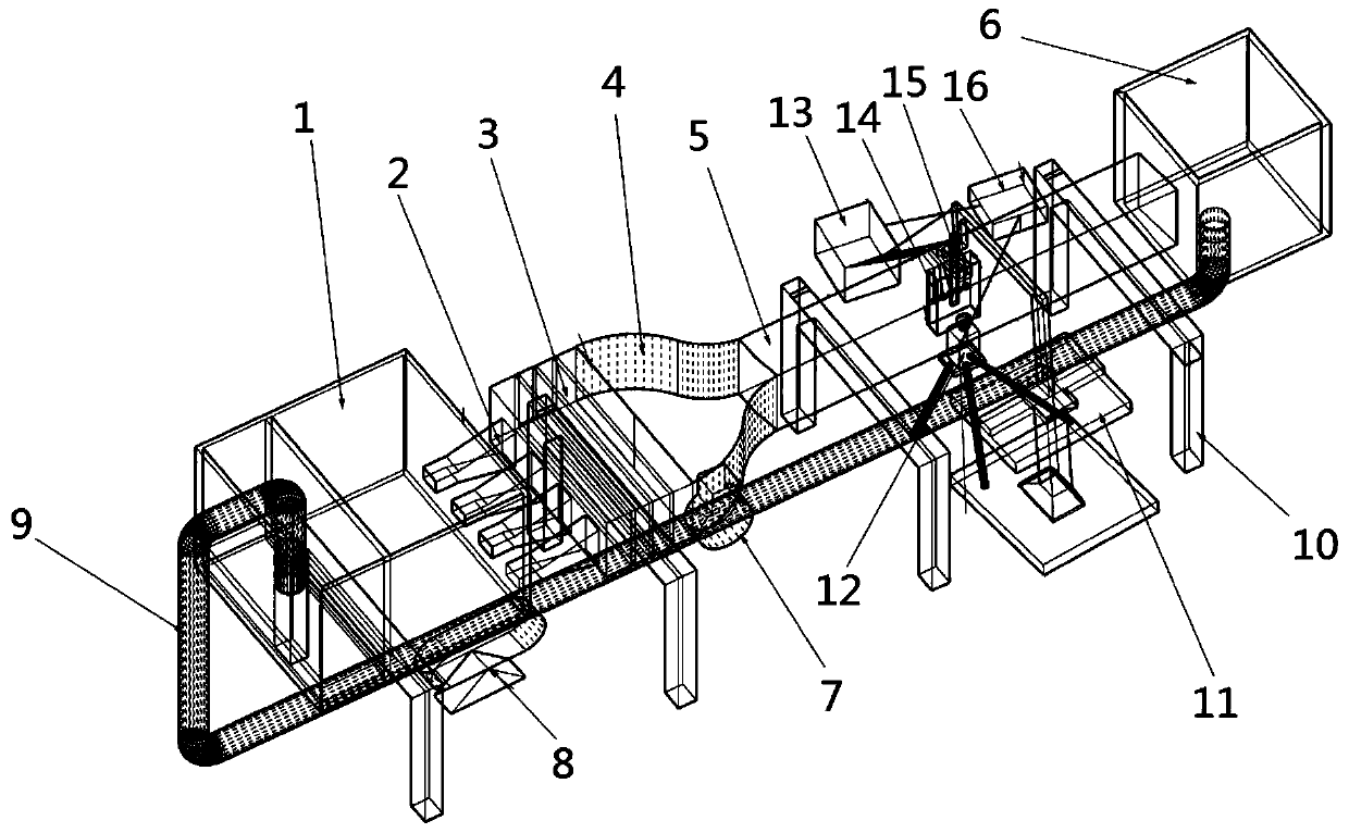
[0031] Embodiment: A test device for flow-induced vibration around a blunt body with pressure and high chord-thickness ratio, including a water circulation part and a test measurement part.

[0032] The water circulation part includes the water storage tank 1, the diffusion pipe group 2, the rectification section water tank 3, the contraction section water tank 4, the test section water tank 5 and the return water tank 6 connected in sequence, and the water storage tank 1 and the return water tank 6 are connected through the return pipe 9 , the return pipe 9 is provided with a water pump 8 and an electromagnetic flowmeter 7, the water flow in the return pipe 9 is measured by the electromagnetic flowmeter 7, and the flow rate of the water in the return pipe 9 is adjusted by changing the power of the water pump 8. The water flow in the water circulation part circulates under the action of the water pump 8 . Water storage tank 1, diffusion pipe group 2, rectification section wate...


PUM


Abstract

The invention discloses a pressure high chord thickness ratio empty box bluff body streaming flow induced vibration test device. An empty box is arranged in a test section water tank, the empty box isof a cuboid, cylinder or irregular structure with openings in the top end and the bottom end, and holes consistent in size and shape are formed in the portion, corresponding to the opening area in the top end of the empty box, of a top plate of the test section water tank; a test measurement part is arranged outside the test section water tank, and comprises a vibration displacement measurement system, a micro pulsating pressure sensor array, a PIV system, a multifunctional dynamic measurement instrument and a synchronous clock; oscillating bar vibration signals obtained by the vibration displacement measurement system and water flow pulsating pressure change signals detected by the micro pulsating pressure sensor array are transmitted to the multifunctional dynamic measuring instrument respectively and recorded, and signals of the multifunctional dynamic measurement instrument and the PIV system are synchronized through the synchronous clock. The device has the advantages of both contact measurement and non-contact measurement, and improves the precision of vibration displacement measurement while not interfering with a flow field.

Description

technical field [0001] The invention belongs to the field of fluid-solid coupling vortex-induced vibration tests, and relates to a test device for synchronously measuring pulsating pressure, vibration displacement and flow field of a blunt body flowing around a wall surface. Background technique [0002] In the study of flow around a bluff body, due to the limitation of measurement means, the measurement of the vibration displacement response of underwater structures has always been a difficult point. [0003] At present, the vibration measurement of structures is mainly divided into contact measurement and non-contact measurement. Among them, the contact measurement includes the second integral of the acceleration sensor and the linear displacement sensor. Non-contact measurement mainly includes laser displacement sensors, eddy current sensors, and magnetostrictive displacement sensors. However, in the test of flow around a blunt body under pressure, the above-mentioned m...

Claims


Application Information

Patent Timeline
IPC IPC(8): G01M10/00G01M7/02G01H9/00
CPCG01H9/00G01M7/02G01M7/025G01M10/00
Inventor 侍贤瑞严根华董家朱春玥孙云茜
Owner NANJING HYDRAULIC RES INST
Why Eureka
Try Eureka