Positioning structure and method of in-mould injection molding steel sheet

A technology of positioning structure and in-mold injection molding, applied in the direction of coating, can solve the problems of poor production, thin wall thickness, warping of injection molding steel sheets, etc., and achieve the effect of preventing warping and deviation

Inactive Publication Date: 2015-07-15
HUIZHOU TCL MOBILE COMM CO LTD
View PDF1 Cites 0 Cited by
  • Summary
  • Abstract
  • Description
  • Claims
  • Application Information

AI Technical Summary

Problems solved by technology

[0002] Some current clamshell machines have small screens, and the size of the small screens is getting larger and larger, with the largest reaching 1.44 inches. However, because the thickness of the whole machine is relatively thin, this leads to a relatively thick wall thickness of the housing with the small screen. Thin, can only be used as in-mold injection molded steel sheet
The exterior lens of a small screen generally needs to be centered to make the width of the black edge of the lens in the window area consistent, so as to achieve a good aesthetic effect, but the steel sheet injected in the mold is too small because the window area is too small, and the positioning hole cannot be made. The perforation leads to unstable positioning of the steel sheet, which is easy to cause problems such as curling and misalignment of the injection-molded steel sheet, causing a series of poor production problems

Method used


Image

  • Positioning structure and method of in-mould injection molding steel sheet
  • Positioning structure and method of in-mould injection molding steel sheet
  • Positioning structure and method of in-mould injection molding steel sheet

Examples


Embodiment 1

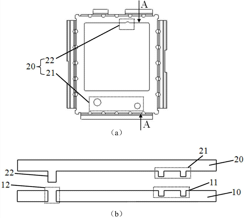
[0026] figure 1 It is a schematic diagram of the positioning structure of the in-mold injection-molded steel sheet according to Embodiment 1 of the present invention, (a) is a front view, and (b) is a schematic cross-sectional view of Figure (a) in the direction A-A.

[0027] refer to figure 1 In (a), (b), the positioning structure of the in-mold injection-molded steel sheet according to Embodiment 1 of the present invention includes: a steel sheet 10 and a mold 20 for positioning the steel sheet 10, wherein the steel sheet 10 is included in the steel sheet The first positioning hole 11 and the second positioning hole 12 in the direction perpendicular to the steel sheet 10 are respectively provided at both ends of the Y direction of the sheet, that is, the first positioning hole 11 and the second positioning hole 12 penetrate through the steel sheet 10. Z direction; the mold 20 includes a first positioning piece 21 and a second positioning piece 22 matched with the first posi...

Embodiment 2

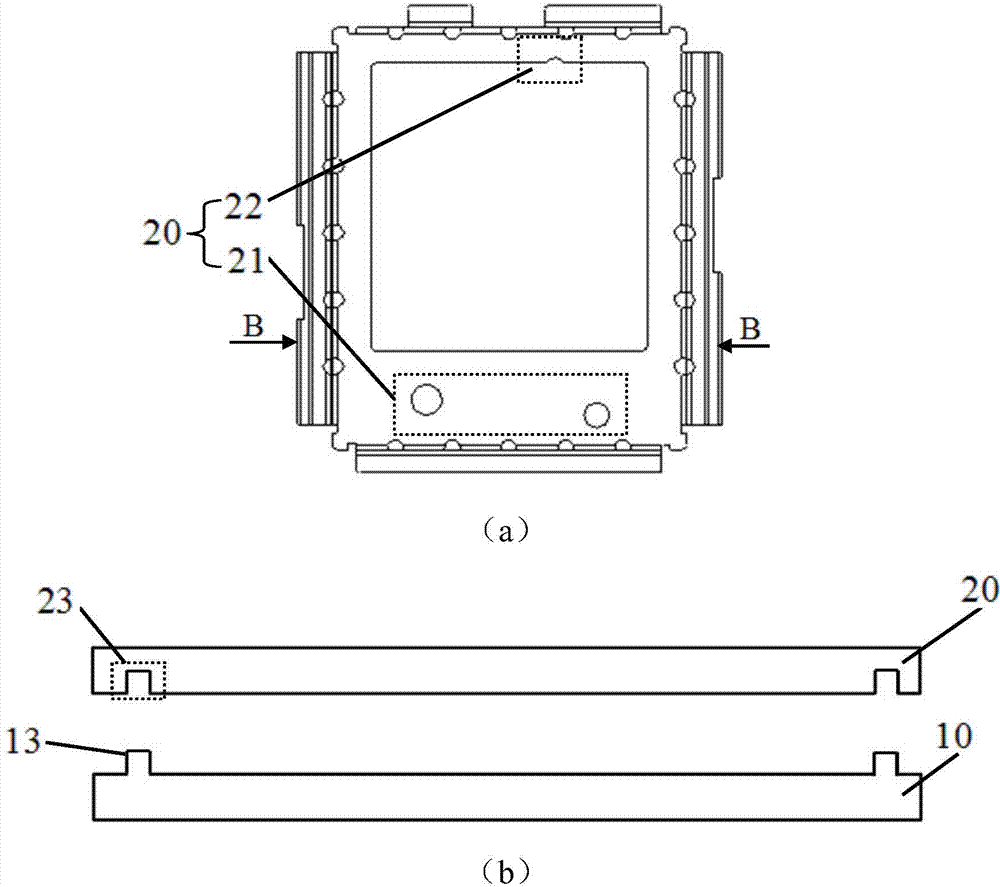
[0036] In the description of Embodiment 2, the similarities with Embodiment 1 will not be repeated here, and only the differences with Embodiment 1 will be described. The difference between embodiment 2 and embodiment 1 is that, referring to image 3 , where (a) is the main view, and (b) is a schematic cross-sectional view of Figure (a) in the B-B direction; the steel sheet 10 also includes clips 13 extending toward both ends in the X direction, and correspondingly, the mold 20 also includes for Corresponding to the card slot 23 of the card member 13; wherein, since the figure (a) is a view from the top view, the card member 13 and the card slot 23 cannot be seen.

[0037] Specifically, the clip 13 is a protrusion facing the Z direction of the steel sheet 10, so that the protruding clip 13 can be correspondingly clamped in the slot 23, so that the slot 23 firmly "bites" the clip 13. live" to prevent the steel sheet 10 from being deflected in the X direction.

[0038] Corresp...

Embodiment 3

[0042] In the description of Embodiment 3, the similarities with Embodiment 1 will not be repeated here, and only the differences with Embodiment 1 will be described. combine figure 1 The schematic diagram of the positioning structure of the injection-molded steel sheet in the mold, the difference between embodiment 3 and embodiment 1 is that the mold 20 also includes positioning columns 24 that are clamped at both ends of the steel sheet 10 in the Y direction and point to the Z direction, as Figure 5 shown.

[0043] In the present embodiment, there are five positioning columns 24, including three positioning columns ( Figure 5 shown in the dotted line box), and the other end opposite to it is distributed with other two positioning columns (not shown in the figure).

[0044] Correspondingly, Image 6 It is a flow chart of the steps of the positioning method for the in-mold injection-molded steel sheet according to Embodiment 3 of the present invention.

[0045] refer to ...


PUM


Abstract

The invention discloses a positioning structure of an in-mould injection molding steel sheet. The positioning structure of the in-mould injection molding steel sheet comprises a steel sheet and a mold used for positioning the steel sheet, wherein the steel sheet comprises a first positioning hole formed in one end vertical to the direction of the steel sheet and a second positioning hole formed in the other end opposite to the end vertical to the direction of the steel sheet; the mold comprises a first positioning part matched with the first positioning hole and a second positioning part matched with the second positioning hole; specifically, the first positioning part is inserted into the first positioning hole; the second positioning part is inserted into the second positioning hole. The invention also discloses a positioning method of the in-mould injection molding steel sheet. The positioning method of the in-mould injection molding steel sheet comprises the following steps: inserting the first positioning part on the mold for positioning the steel sheet into the first positioning hole of the steel sheet; and inserting the second positioning part of the mold into the second positioning hole of the steel sheet. The positioning structure and method of the in-mould injection molding steel sheet can be used for positioning the steel sheet in the three-dimensional direction, so that the unfavorable conditions that the steel sheet curls and deviates can be effectively avoided.

Description

technical field [0001] The invention belongs to the technical field of mold injection molding processing, and in particular relates to a positioning structure and method for an in-mold injection-molded steel sheet that prevents the steel sheet from warping and shifting. Background technique [0002] Some current clamshell machines have small screens, and the size of the small screens is getting larger and larger, with the largest reaching 1.44 inches. However, because the thickness of the whole machine is relatively thin, this leads to a relatively thick wall thickness of the housing with the small screen. Thin, can only be used as in-mold injection-molded steel sheet. The exterior lens of a small screen generally needs to be centered to make the width of the black edge of the lens in the window area consistent, so as to achieve a good aesthetic effect, but the steel sheet injected in the mold is too small because the window area is too small, and the positioning hole cannot...

Claims


Application Information

Patent Timeline
Patent Type & Authority Applications(China)
IPC IPC(8): B29C45/14B29C45/26
Inventor 杨治
Owner HUIZHOU TCL MOBILE COMM CO LTD
Why Eureka
Try Eureka