One-way adjustable chain type conveying mechanism

A technology of conveying mechanism and adjustable chain, which is applied in the direction of conveyor, transportation and packaging, etc. It can solve the problems such as the distance between the two chains cannot be adjusted, the conveyor chain moves back, and the adjustment efficiency is low, so as to shorten the preparation time, prevent excessive rotation, Good braking effect

Active Publication Date: 2015-07-15
宁波宫铁智能科技有限公司
View PDF7 Cites 5 Cited by
  • Summary
  • Abstract
  • Description
  • Claims
  • Application Information

AI Technical Summary

Problems solved by technology

[0003] The existing conveyor chain includes a frame and two chains. A transmission shaft is arranged on the frame. Two gears are arranged on the transmission shaft. The two chains are arranged on the two gears. The other end of the chain is sleeved on the driving device to drive the chain. When the gear is rotating, there is also a material holder on the chain that can pick up the workpiece. This kind of conveyor chain can realize the transfer of the workpiece on the processing equipment, but there are the following technical problems at the same time. 1. The existing conveyor chain will The workpiece is conveyed from the low to the high place, and the conveying of the workpiece is uninterrupted, which may easily lead to the disorder of the conveying of the workpiece; 2. This kind of conveying chain has no brake device, and the workpiece will easily cause the conveying chain to move back under the condition of its own weight, resulting in low conveying efficiency , and the conveyor chain keeps moving, it is easy to miss the situation when the workpiece is conveyed; 3. The distance between the two chains in the existing conveyor chain cannot be adjusted, or there is only one chain between the two chains. When it is necessary to adjust the distance between the two chains to meet the needs of conveying workpieces of different widths, it takes a long time to adjust one chain, which makes the adjustment efficiency lower, increases the preparation work before conveying, and delays more conveying time

Method used


Image

  • One-way adjustable chain type conveying mechanism
  • One-way adjustable chain type conveying mechanism
  • One-way adjustable chain type conveying mechanism

Examples


Embodiment Construction

[0033] The following are specific embodiments of the present invention and in conjunction with the accompanying drawings, the technical solutions of the present invention are further described, but the present invention is not limited to these embodiments.

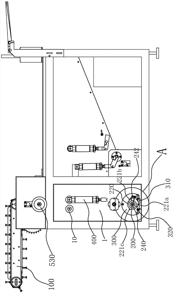
[0034] For ease of understanding, Figure 5 The arrows in indicate the direction of rotation of the transmission shaft, ratchet, and turntable, which is reverse rotation.

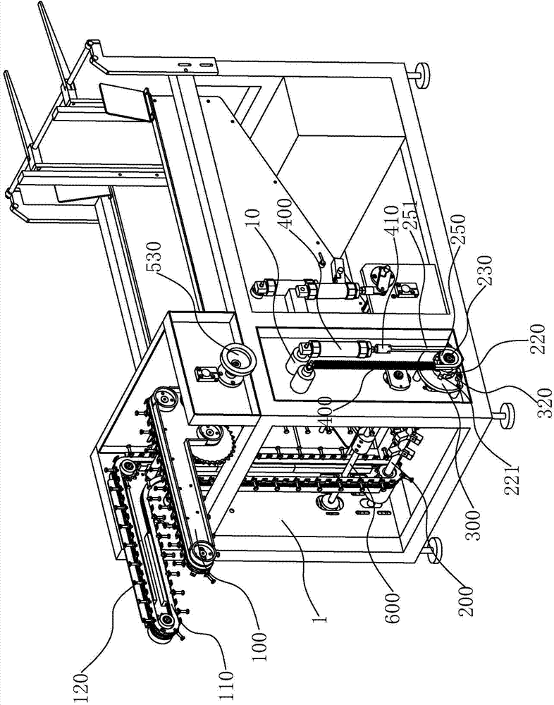
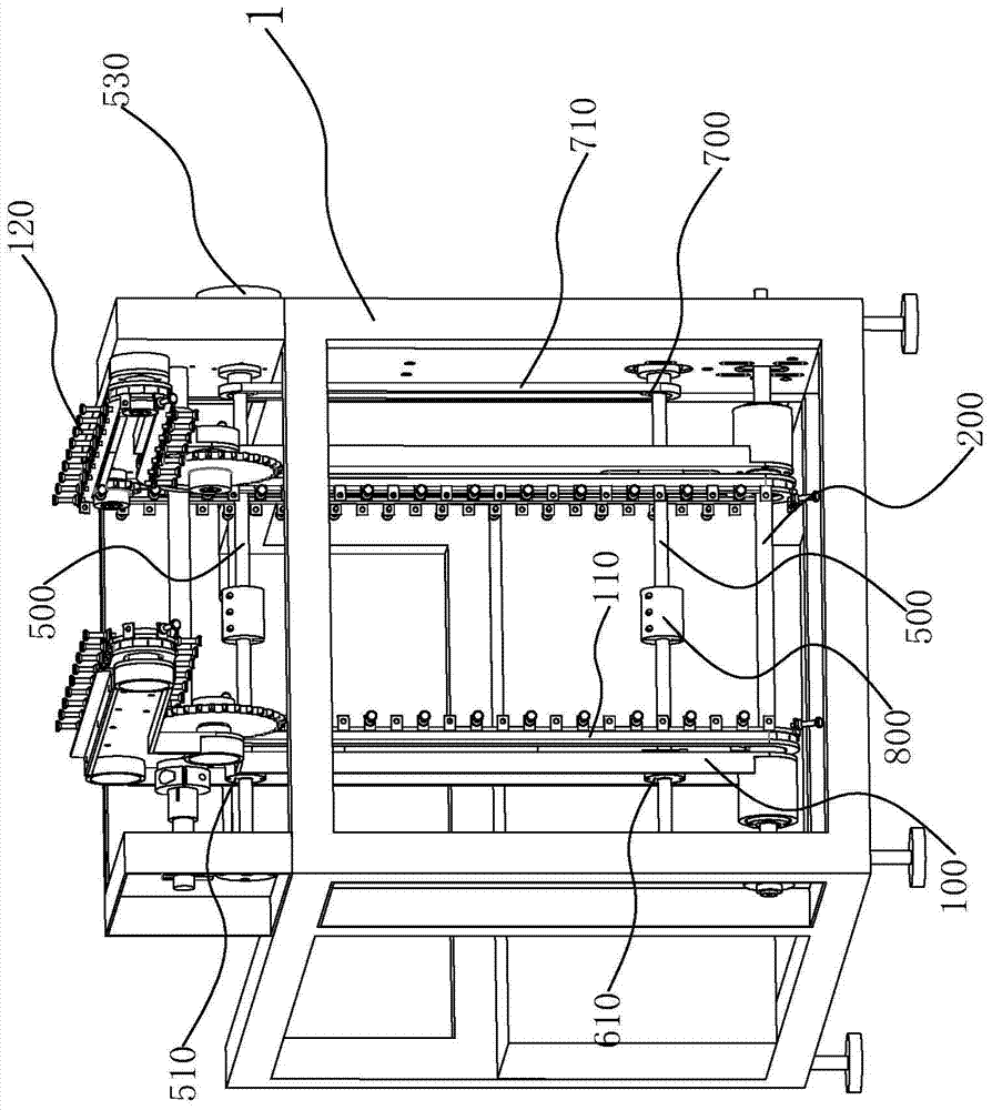
[0035] Such as Figure 1 to Figure 4 As shown, a one-way adjustable chain conveying mechanism of the present invention is installed on the frame 1, and includes two vertical and parallel chain plate frames 100 and a transmission shaft 200 passing through the two chain plate frames 100, and the two chain plate frames 100 is located in the frame, conveyor chains 110 are installed on the two chain plate frames 100 respectively, the two ends of the transmission shaft 200 are connected with the frame 1 respectively, and two ends in the frame are respectivel...


PUM


Abstract

The invention provides a one-way adjustable chain type conveying mechanism, belongs to the technical field of automatic machining, and solves the technical problems of disorder and missing during conveying of workpieces with the conventional conveying chain. The one-way adjustable chain type conveying mechanism comprises a link plate frame, a transmission shaft, a transmission device, an arresting device and an adjusting device, wherein a conveying chain is arranged on the link plate frame; a ratchet wheel is arranged on the transmission shaft; the ratchet wheel is provided with a plurality of gear blocks; the transmission device is used for driving the ratchet wheel to rotate and move the conveying chain; when the gear blocks are in contact with the arresting device, the ratchet wheel stops rotating; when the transmission device drives the arresting device to move away from the gear blocks, the ratchet wheel can rotate continually; the adjusting device is connected with the link plate frame, and can drive the link plate frame to move on the transmission shaft. The one-way adjustable chain type conveying mechanism has the beneficial effects that the ratchet wheel is driven to rotate through the transmission device, so that the workpieces can be conveyed orderly. Bidirectional braking of the ratchet wheel is realized in the static state of the ratchet wheel through the arresting device, so that the workpiece conveying accuracy is ensured.

Description

technical field [0001] The invention belongs to the technical field of automatic processing, and relates to a chain conveying mechanism, in particular to a one-way adjustable chain conveying mechanism. Background technique [0002] In the existing automatic processing equipment, the conveyor chain is usually used to send the workpiece to the processing end for processing or to transport the processed workpiece from the processing end to the receiving end, and the workpiece is transported through the conveyor chain, which improves the overall processing efficiency of the automatic processing equipment. [0003] The existing conveyor chain includes a frame and two chains. A transmission shaft is arranged on the frame. Two gears are arranged on the transmission shaft. The two chains are arranged on the two gears. The other end of the chain is sleeved on the driving device to drive the chain. When the gear is rotating, there is also a material holder on the chain that can pick u...

Claims


Application Information

Patent Timeline
Patent Type & Authority Applications(China)
IPC IPC(8): B65G23/40B65G21/12B65G17/00
CPCB65G21/12B65G23/40
Inventor 杨云林
Owner 宁波宫铁智能科技有限公司
Why Eureka
Try Eureka