Movement Control Device, Movement Control Method And Numerical Control Device

A control device and control object technology, applied in the direction of digital control, electrical program control, control using feedback, etc., can solve the problem that the numerical control device is difficult to perform multiple intervals

Active Publication Date: 2014-08-06
BROTHER KOGYO KK
View PDF12 Cites 0 Cited by
  • Summary
  • Abstract
  • Description
  • Claims
  • Application Information

AI Technical Summary

Problems solved by technology

Therefore, it is difficult for the numerical control device to

Method used


Image

  • Movement Control Device, Movement Control Method And Numerical Control Device
  • Movement Control Device, Movement Control Method And Numerical Control Device
  • Movement Control Device, Movement Control Method And Numerical Control Device

Examples


Embodiment approach 1

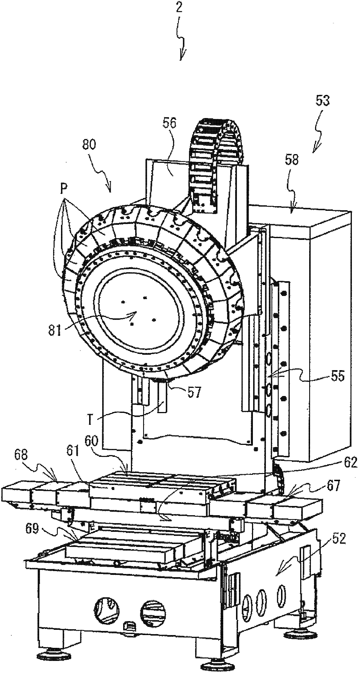
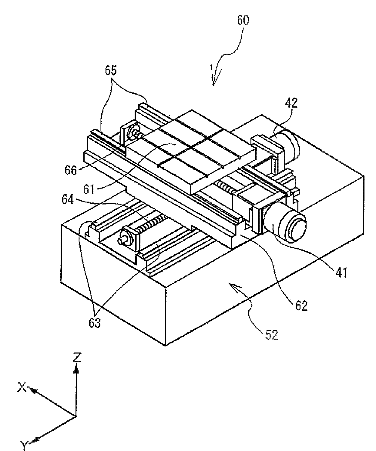
[0019] Embodiments of the present invention will be described below with reference to the drawings. The machine tool 2 includes a base 52, a machine tool body 53, an XY table mechanism 60, a tool changing device 80, and the like. The base 52 is a substantially cuboid base made of iron. The machine tool body 53 is provided behind the upper part of the base 52 and cuts a workpiece (not shown) held on the upper surface of an X table 61 described later. The XY platform mechanism 60 is located at the center of the upper part of the base 52 , which drives the X platform 61 toward the X-axis direction and the Y-axis direction. The tool changing device 80 is provided on the upper part of the machine tool body 53 , and replaces the tool T attached to the spindle 57 of the machine tool body 53 . Next, the structure of the machine tool main body 53 will be described. The main body 53 of the machine tool includes a column 55 , a spindle head 56 , a spindle 57 , a control box 58 and the...

Embodiment approach 2

[0029] In Embodiment 2, the control unit 10 also performs processing of changing the average speed based on signals of a plurality of periods.

[0030] The control unit 10 of Embodiment 2 counts the number of times the input unit 17 outputs a signal within a predetermined period constituted by N times a certain time. When the number of signals counted within the period is equal to or greater than a predetermined value and the number of signals counted in a predetermined period (previous period) before this period is also equal to or greater than a predetermined value, the control unit 10 performs the following control. The control unit 10 calculates the integrated value of the movement amount indicated by the signal output during the period and the previous period. The control unit 10 divides the calculated integrated value by 2N (N+N). The control unit 10 outputs a signal for continuously moving the movement control object at an average speed based on the value obtained by t...


PUM


Abstract

The invention provides a movement control device, a movement control method and a numerical control device used for controlling movement of a control object. The movement control device counts the frequency of outputting signals from an operation part operating the movement of the movament control object in a specific period. When the frequency is smaller than a predetermined value, the movement of the movement control object is controlled based on an accumulative value obtained through accumulation of values indicated by signals output in the period. When the frequency is greater than the predetermined value, the movement of the movement control object is controlled based on an average value of the accumulative value obtained through accumulation of values indicated by signals output in the period.

Description

technical field [0001] The invention relates to a movement control device, a movement control method and a numerical control device for controlling the movement of a control object. Background technique [0002] As machine tools for processing machine parts, there are lathes, drill machines, grinders, and the like. This machine tool processes machine parts by controlling the movement of a machining tool for machining workpieces such as metals and a part (movement control object) that fixes the workpiece. A machine tool includes a numerical control device that controls a moving control object. The numerical control device predetermines the movement amount of the movement control object, and moves the movement control object based on numerical information representing the determined movement amount (for example, Japanese Patent Laid-Open Publication No. Hei 4-7609 and Japanese Patent Laid-Open Publication No. 2004-306158) . As a method of moving the movement control object,...

Claims


Application Information

Patent Timeline
IPC IPC(8): G05D3/12G05B19/18
Inventor 白﨑宏行
Owner BROTHER KOGYO KK
Why Eureka
Try Eureka