A yoke-type local micro-magnetization detection device suitable for point defects

A detection device and yoke technology, which is applied in the direction of material magnetic variables, etc., can solve the problem of being unable to detect weak magnetic field signals such as "point" pits and scratches, unable to adapt to environmental detection requirements, and easily damaging the surface of soft parts To achieve the effect of reducing magnetization work, accurate online monitoring, and improving accuracy and efficiency

Active Publication Date: 2017-06-27
HUAZHONG UNIV OF SCI & TECH +1
View PDF3 Cites 0 Cited by
  • Summary
  • Abstract
  • Description
  • Claims
  • Application Information

AI Technical Summary

Problems solved by technology

However, the above detection methods have certain limitations. The contact method is easy to damage the surface of soft parts and is ineffective for surface oblique and deep wrinkles. However, the optical non-contact method is affected by the ambient brightness and has low detection accuracy.
[0003] In short, the existing detection methods require the object to be inspected to have a specific surface cleanliness and static state, which cannot meet the harsh environmental detection requirements during part processing. The residual magnetism is relatively weak, and the existing magnetic induction devices cannot detect weak magnetic field signals such as tiny "point" type pits and scratches. Therefore, in order to break through the tiny "point" type It is of great significance to invent a high-resolution point-type magnetic induction device to detect defects and meet the requirements of online monitoring of working conditions and environments.

Method used


Image

  • A yoke-type local micro-magnetization detection device suitable for point defects
  • A yoke-type local micro-magnetization detection device suitable for point defects
  • A yoke-type local micro-magnetization detection device suitable for point defects

Examples


Embodiment Construction

[0022] In order to make the object, technical solution and advantages of the present invention clearer, the present invention will be further described in detail below in conjunction with the accompanying drawings and embodiments. It should be understood that the specific embodiments described here are only used to explain the present invention, not to limit the present invention. In addition, the technical features involved in the various embodiments of the present invention described below can be combined with each other as long as they do not constitute a conflict with each other.

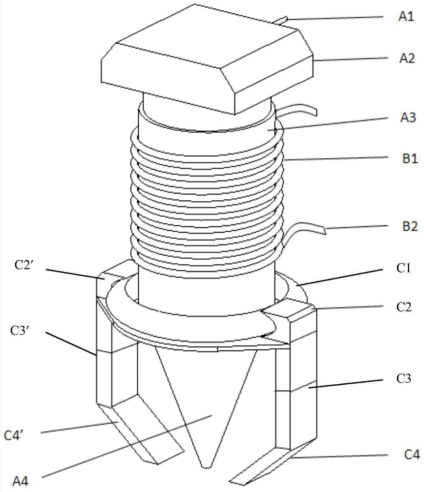
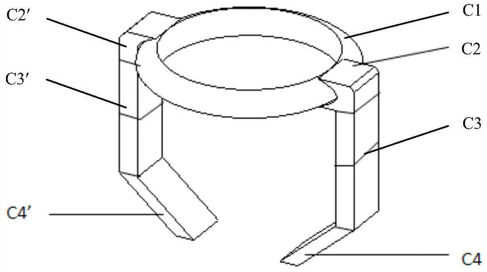
[0023] Such as figure 1 As shown, a yoke-type local micro-magnetization detection device suitable for point defects includes a magnetic sensitive element part A, a magnetic induction part B and a yoke-type local micro-magnetization part C.

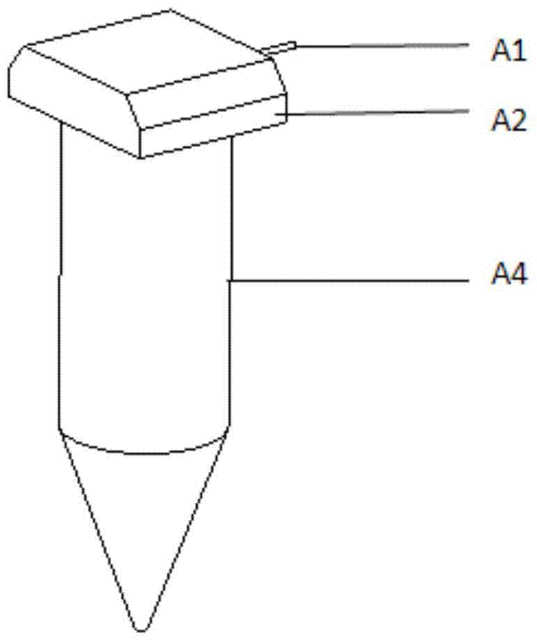
[0024] Among them, the magnetic sensitive element part A is composed of the magnetic sensitive element lead terminal A1, the magnetic sensitive element A2 ...


PUM


Abstract

The invention discloses a yoke-type local micro-magnetization detection device suitable for point defects. The device includes a magnetic sensitive element part, a magnetic induction part and a yoke-type local micro-magnetization part. The magnetic sensitive element part includes a magnetic sensitive element and a lead wire end, magnetic guide core and guide core sleeve, the lower end of the magnetic guide core adopts a conical structure to refine the detection area to achieve high-resolution detection of point defects; the magnetic induction part is composed of a magnetic induction coil wound outside the guide core sleeve ; The yoke-type local micro-magnetization part supported and fixed by the guide core sleeve includes a ring-shaped magnetic-conductive member, a magnet connector, a yoke-type double magnet and an oblique double magnetic-conductive member. This part guides the magnetic field into the metal body to be detected , to achieve the effect of local micro-magnetization, through the magnetic sensitive element connected with the magnetic guide core or the magnetic induction coil outside the guide core sleeve, the signal of the leakage field quantity signal of the point defect on the surface of the metal part is transmitted, and the surface / interface shape of the high-precision metal part is realized. sexual detection.

Description

technical field [0001] The invention belongs to the technical field of non-destructive detection of point defects on the surface / interface of metal parts, and more specifically relates to a yoke-type local micro-magnetization detection device suitable for point defects. Background technique [0002] Due to the complex physical phenomena induced by force-thermal coupling and other loads during the processing of high-precision metal parts, the surface / interface shape of the part is greatly affected. Therefore, it is necessary to detect the surface condition of the part itself. The methods for detecting surface topography include contact methods such as stylus method and impression method, and optical non-contact methods. However, the above detection methods have certain limitations. The contact method is easy to damage the surface of soft parts and is ineffective for surface oblique and deep wrinkles, while the optical non-contact method is affected by the ambient brightness a...

Claims


Application Information

Patent Timeline
Patent Type & Authority Patents(China)
IPC IPC(8): G01N27/82
Inventor 孙燕华刘世伟冯搏顾民刘长德康宜华陈少波
Owner HUAZHONG UNIV OF SCI & TECH
Why Eureka
Try Eureka