Supercharge Your Innovation With Domain-Expert AI Agents!

Radiation detection device and manufacturing method therefor

A radiation detection and radiation technology, applied in the field of radiation detection devices, can solve problems such as uneven lighting, narrowing of space, and clear shooting obstacles.

Inactive Publication Date: 2015-07-15
TORAY IND INC
View PDF12 Cites 6 Cited by
  • Summary
  • Abstract
  • Description
  • Claims
  • Application Information

AI Technical Summary

Problems solved by technology

However, when the width of the partition wall becomes larger, the space between the partition walls becomes relatively narrow, the volume that can be filled with the X-ray phosphor becomes smaller, and the filling amount does not become uniform.
Therefore, the amount of X-ray phosphors in the scintillator panel obtained by this method is small, so there are disadvantages such as weak light emission and uneven light emission.
They are an obstacle to clear shots in low dose shots

Method used


Image

  • Radiation detection device and manufacturing method therefor
  • Radiation detection device and manufacturing method therefor

Examples


Embodiment 1)

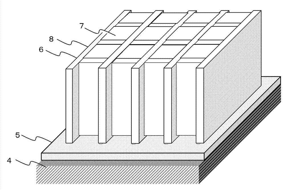
[0132] On a glass substrate of 500 mm x 500 mm ("OA-10" manufactured by NEC Glass Co., Ltd.), apply a photosensitive paste for partition walls by die coating so that the dry thickness is 500 μm, and dry to form a photosensitive paste for partition walls. Apply film. Next, through a photomask (a chromium mask having grid-shaped openings with a pitch of 125 μm and a line width of 10 μm) formed with openings corresponding to a desired partition pattern, a 700 mJ / cm 2 The photosensitive paste coating film for partition walls was exposed to the exposure amount of . The photosensitive paste coating film for partition walls after exposure was developed in 0.5 mass % of ethanolamine aqueous solution, the unexposed part was removed, and the photosensitive paste coating film pattern of grid shape was formed. Furthermore, the photosensitive paste coating film pattern was sintered in the air at 585° C. for 15 minutes, and the interval L2 with partition walls formed on the surface was 125...

Embodiment 2)

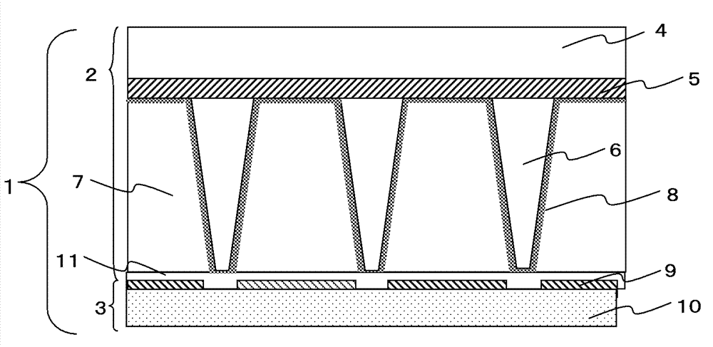
[0138] A substrate on which lattice-shaped partition walls were formed was produced by the same method as in Example 1. Thereafter, an aluminum film, that is, a reflective film, was formed on the surface of the partition wall and the surface of the substrate where the partition wall was not formed by a intermittent sputtering device ("SV-9045" manufactured by ULVAC). The formed aluminum film had a thickness of 300 nm at the top of the partition wall, a thickness of 100 nm of the aluminum film on the side of the partition wall, and a thickness of 100 nm of the aluminum film on the substrate.

[0139] Next, after mixing gadolinium oxysulfide powder with a particle size of 5 μm and a refractive index of 2.2 as a phosphor with ethyl cellulose with a refractive index of 1.5, it is filled in the space defined by the partition wall to produce a phosphor in the cell. Scintillator panels with a volume fraction of 90%. Using the produced scintillator panel, by the same method as in Exa...

Embodiment 3)

[0141] Except having changed the glass substrate of Example 1 into the tungsten substrate (made by Applied Materials) of 300x300 mm, the radiation detection apparatus was produced and evaluated by the method similar to Example 1. As a result, the X-rays transmitted through the radiation detection device are absorbed by the tungsten substrate, so the noise is reduced, and the brightness is 110 and the resolution is 165, both of which are good values.


PUM


Abstract

The present invention provides a radiation detection device wherein narrow-width partitions are formed with high accuracy in a large area and high light emission efficiency and a clear image quality are achieved. The present invention provides a radiation detection device having a configuration in which a substrate on the surface of which partitions are formed and a light detector face each other, wherein cells demarcated by the partitions are formed in a space between the substrate and the light detector, the cells are filled with phosphor, light detection pixels are provided on the surface of the light detector with which the partitions are not in contact, and an adhesion layer is formed between the partitions and the phosphor, and the light detector.

Description

technical field [0001] The present invention relates to a radiation detection device used in medical diagnostic devices, non-destructive inspection equipment, and the like. Background technique [0002] Conventionally, X-ray images using thin films have been widely used at medical sites. However, X-ray images using thin films are analog image information. Therefore, in recent years, digital radiation detection systems such as computed radiography (CR) and flat panel detectors (flat panel detector: FPD) have been developed. detection device. [0003] In a flat panel X-ray detection device (FPD), a scintillator panel is used to convert radiation into visible light. The scintillator panel contains X-ray phosphors such as cesium iodide (CsI), which emit visible light according to the irradiated X-rays, and uses TFT (thin film transistor: thin film transistor), CCD (charge-coupled device: charge-coupled device) converts the light into an electrical signal, thereby converting t...

Claims


Application Information

Patent Timeline
Patent Type & Authority Applications(China)
IPC IPC(8): G01T1/20
CPCG01T1/2018G01T1/20183G01T1/2019G01T1/2002H01L31/02322H01L27/14685H01L27/14623H01L27/14663
Inventor 冈村昌纪井口雄一朗村井尚宏
Owner TORAY IND INC
Features
  • R&D
  • Intellectual Property
  • Life Sciences
  • Materials
  • Tech Scout
  • Unparalleled Data Quality
  • Higher Quality Content
  • 60% Fewer Hallucinations
Learn More