
Electricity storage device

A technology for power storage equipment and battery modules, which is applied to batteries, circuits, electrical components, etc., can solve the problems of large size and low energy density, and achieve the effect of ensuring vibration resistance and realizing replaceability

Active Publication Date: 2015-07-15
ENVISION AESC ENERGY DEVICES LTD
View PDF17 Cites 7 Cited by
  • Summary
  • Abstract
  • Description
  • Claims
  • Application Information

AI Technical Summary

Problems solved by technology

Generally, lead batteries are used as batteries for storing clean energy, but the disadvantages of lead batteries are that they are usually large in size and have low energy density

Method used


Image

  • Electricity storage device
  • Electricity storage device
  • Electricity storage device

Examples


Embodiment Construction

[0056] Embodiments of the present invention will be described below with reference to the accompanying drawings.

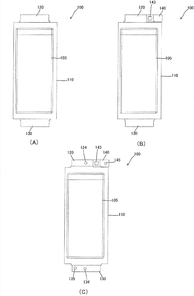
[0057] figure 1 is a view showing the unit cells 100 constituting the battery module and their preparatory processing procedures. As the unit cell 100 , a lithium ion secondary battery is used as an electrochemical element in which lithium ions move between positive and negative electrodes to perform charge and discharge.

[0058] figure 1 A shows the unit cell 100 before preparatory processing. In the structure of the battery main body 110 of the unit cell 100, an electrode stack (not shown) obtained by laminating a plurality of plate-shaped positive electrodes and a plurality of plate-shaped negative electrodes through a separator and an electrolyte (not shown) are housed in In a laminated film exterior material with a rectangular plan. One end (side) of the battery main body 110 and the other end (side) facing the one end are provided with a positive electrod...


PUM


Abstract

To provide a power storage device having both replaceability of a battery module and excellent vibration resistance / impact resistance. A power storage device 1300 according to the present invention includes: a bottom plate 1210 having a plurality of lower guide members; a top plate 1220 provided above the bottom plate 1210 and having a plurality of upper guide members facing the lower guide members; a first side plate 1230 and a second side plate 1240 provided between the bottom plate 1210 and the top plate 1220 so as to face each other; a back surface plate provided between the first and second side plates 1230 and 1240 and having a plurality of connectors; a battery module 1000 inserted between the lower and upper guide members and having connectors to be fitted to the connectors of the back surface plate; and a pressing plate 1260 provided between and fixed to the first and second side plates 1230 and 1240 so as to press the battery module 1000.

Description

technical field [0001] The present invention relates to an electric power storage device accommodating a plurality of battery modules each constructed by using a secondary unit battery such as a lithium ion battery. Background technique [0002] In recent years, as a solution to environmental problems, clean energy that can be obtained through wind power generation, solar power generation, etc. and can be used for domestic use (such as isolated houses, etc.) or industrial use (for transportation equipment, construction equipment, etc.) has attracted attention . However, the disadvantage of clean energy is that the output varies greatly depending on the situation. For example, energy from solar power generation can be obtained during the day when the sun is shining, but not at night after sunset. [0003] In order to stabilize the output of clean energy, the technology of temporarily storing clean energy in batteries is used. For example, the solar energy thus stored in th...

Claims


Application Information

Patent Timeline
Patent Type & Authority Applications(China)
IPC IPC(8): H01M2/10H01M2/20H01M50/105H01M50/211H01M50/224H01M50/264H01M50/503H01M50/51H01M50/522
CPCH01M10/613H01M10/0481H01M2/1077H01M10/6561H01M2/206H01M10/647H01M2/1061H01M2/204H01M10/0525H01M10/486H01M50/503H01M50/105H01M50/211H01M50/224H01M50/51H01M50/522H01M50/264Y02E60/10Y02P70/50H01M2220/10H01M2220/20
Inventor 铃木亨
Owner ENVISION AESC ENERGY DEVICES LTD
Learn More