Glass plate substitute film, and display device
a technology of glass plate and substitute film, applied in the direction of electrically conductive paints, synthetic resin layered products, adhesive types, etc., can solve the problems of high demand for reducing thickness, high demand for glass plate replacement, and general fragility of glass plate, and achieve superior impact resistance and light weight, sufficient scratch-preventing properties, and superior substitutability
- Summary
- Abstract
- Description
- Claims
- Application Information
AI Technical Summary
Benefits of technology
Problems solved by technology
Method used
Image
Examples
first embodiment
Glass Plate Substitute Film
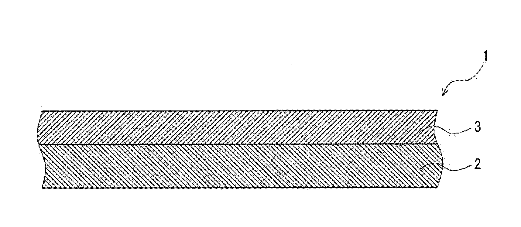
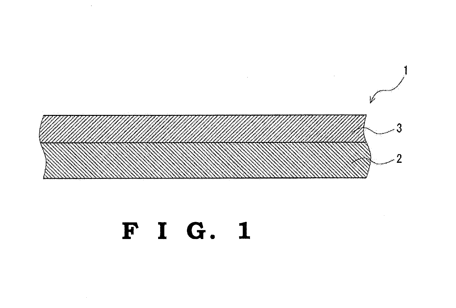
[0030]The glass plate substitute film 1 shown in FIG. 1 includes a substrate layer 2, and a surface layer 3 overlaid on one side of the substrate layer 2. The glass plate substitute film 1 shown in FIG. 1 is formed as a two-layer structure including the substrate layer 2 and the surface layer 3. The glass plate substitute film 1 shown in FIG. 1 is transparent. The glass plate substitute film 1 shown in FIG. 1 is flexible. The glass plate substitute film 1 shown in FIG. 1 is used as a substitute for conventional glass plates. It is to be noted that each figure herein shows a schematic view and the dimension and the like may differ from actual one.
[0031]The lower limit of the average thickness of the glass plate substitute film 1 is preferably 120 μm, more preferably 300 μm, and still more preferably 400 μm. On the other hand, the upper limit of the average thickness of the glass plate substitute film 1 is preferably 1,040 μm, more preferably 800 μm, and sti...
second embodiment
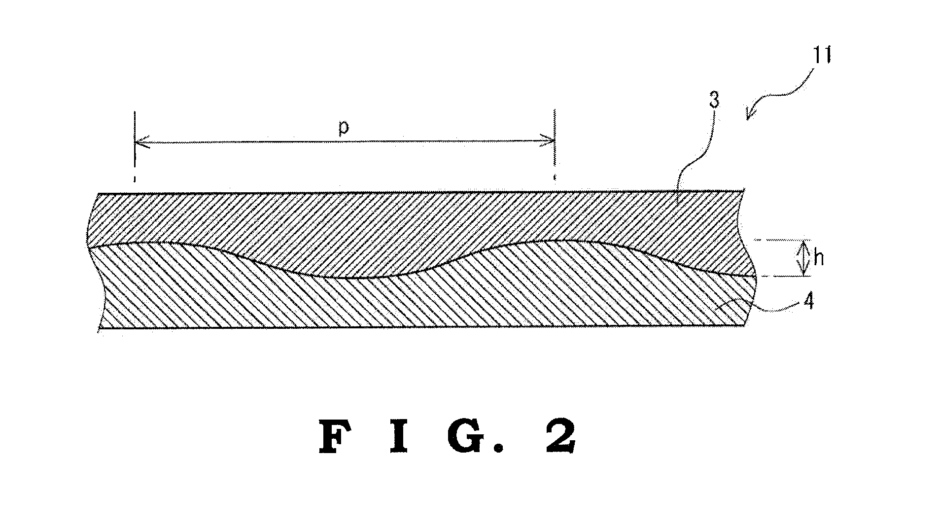
[0092]The glass plate substitute film 11 shown in FIG. 2 includes a substrate layer 4, and the surface layer 3 overlaid on one side of the substrate layer 4 similarly to the first embodiment. The glass plate substitute film 11 shown in FIG. 2 is formed as a two-layer structure composed of the substrate layer 4 and the surface layer 3. Since the surface layer 3 is similar to that in the glass plate substitute film 1 shown in FIG. 1, the description is omitted through designating with the identical reference number. In addition, the average thickness and the pencil hardness of one side face of the glass plate substitute film 11 are similar to those of the glass plate substitute film 1 shown in FIG. 1. The glass plate substitute film 1 shown in FIG. 2 is transparent. The glass plate substitute film 11 shown in FIG. 2 is flexible. The glass plate substitute film 11 shown in FIG. 2 is used as a substitute for conventional glass plates.
[0093]Substrate Layer
[0094]The substrate layer 4 is f...
third embodiment
[0101]The glass plate substitute film 21 shown in FIG. 4 includes the substrate layer 2, a surface layer 5 overlaid on one side of the substrate layer 2, and an adhesion layer 6 provided between the substrate layer 2 and the surface layer 5, whereby the substrate layer 2 and the surface layer 5 are adhered via the adhesive layer 6. The glass plate substitute film 21 shown in FIG. 4 is formed as a three-layer structure including the substrate layer 2, the surface layer 5 and the adhesion layer 6. Since the substrate layer 2 is similar to that in the glass plate substitute film shown in FIG. 1 or FIG. 2, the description is omitted through designating with the identical reference number. In addition, the pencil hardness of one side face of the glass plate substitute film 21 is similar to that of the glass plate substitute film shown in FIG. 1 or FIG. 2. The glass plate substitute film 21 shown in FIG. 4 is transparent. The glass plate substitute film 21 shown in FIG. 4 is flexible. The...
PUM
| Property | Measurement | Unit |
|---|---|---|
| thickness | aaaaa | aaaaa |
| thickness | aaaaa | aaaaa |
| thickness | aaaaa | aaaaa |
Abstract
Description
Claims
Application Information
 - R&D
- Intellectual Property
- Life Sciences
- Materials
- Tech Scout
- Unparalleled Data Quality
- Higher Quality Content
- 60% Fewer Hallucinations
Browse by: Latest US Patents, China's latest patents, Technical Efficacy Thesaurus, Application Domain, Technology Topic, Popular Technical Reports.
© 2025 PatSnap. All rights reserved.Legal|Privacy policy|Modern Slavery Act Transparency Statement|Sitemap|About US| Contact US: help@patsnap.com


