a differential joint

A joint and differential speed technology, which is applied in the direction of manipulators, manufacturing tools, joints, etc., can solve the problems of large volume, low load capacity, and poor stability, and achieve the effect of improving control accuracy, high load capacity, and reducing requirements

Active Publication Date: 2016-12-07
HARBIN ENG UNIV
View PDF6 Cites 0 Cited by
  • Summary
  • Abstract
  • Description
  • Claims
  • Application Information

AI Technical Summary

Problems solved by technology

[0003] In general, the traditional mechanical arm joints have low load capacity, poor stability, large size, and generally can only provide single-degree-of-freedom motion

Method used


Image

  • a differential joint
  • a differential joint
  • a differential joint

Examples


Embodiment Construction

[0017] The present invention will be further described in detail below in conjunction with the accompanying drawings and specific embodiments.

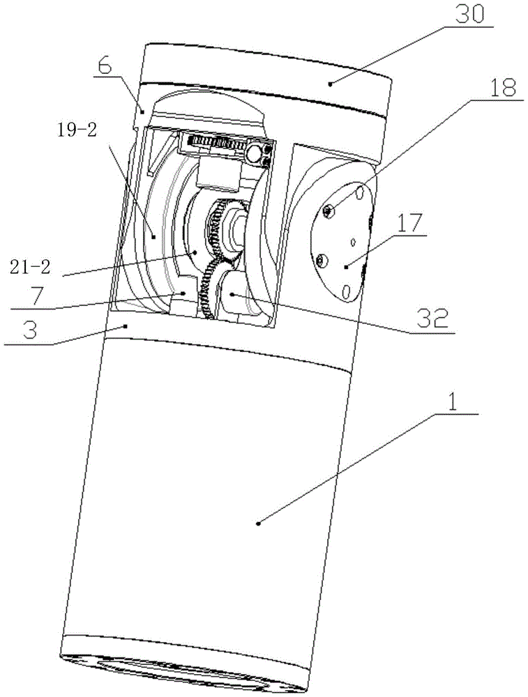
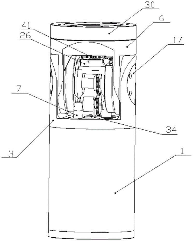
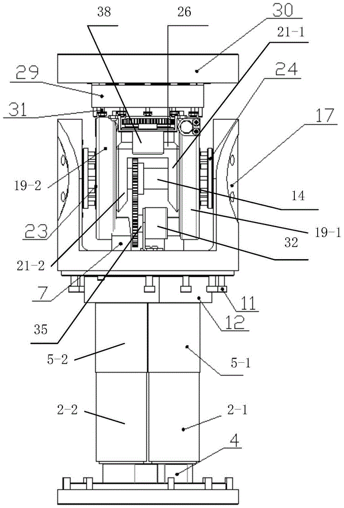
[0018] combine Figure 1 to Figure 7 , the present invention includes a transition connection cylinder 1, a joint support frame 3 installed on the upper end of the transition connection cylinder 1, a main shaft 14 installed in the middle of the joint support frame 3 through two bearing seats 17, and a joint structure frame 6 sleeved on the main shaft 14 And the joint end face flange 30 that is arranged on the joint structure frame 6 upper ends, two motors 2-1 and 2-2 are installed in the transition connecting cylinder 1, the lower end of each motor is connected with the photoelectric encoder 4, each motor The output ends of 2-1 and 2-2 are connected with planetary reducers 5-1 and 5-2, and the output ends of each planetary reducer 5-1 and 5-2 are connected with a gear shaft 7, and the gear shaft 7 The toothed end extends into the joi...


PUM


Abstract

The invention provides a differential joint. The differential joint comprises a transitional connection barrel, a motor drive device, a joint supporting frame, a differential mechanism and a joint structure frame, wherein the motor drive device is fixed to the transitional connection barrel, and the differential mechanism and the joint structure frame are arranged on the joint supporting frame. The drive device comprises motors, an optical-electricity encoder and planetary reducers. The differential mechanism comprises gear shafts, hypoid gears and bevel gears. The joint can swing forwards and backwards and rotates leftwards and rightwards through control over forward and backward rotation of the two motors, the two motors reversely rotate to control the joint to swing forwards and backwards, and the two motors rotate in the same direction to control the joint to rotate leftwards and rightwards. Meanwhile, potentiometers installed on the joint supporting frame and the joint structure frame can perform feedback control over the motion speed of the joint, and the different joint is used for an MDOF mechanical arm. The differential joint is compact in structure and high in load capacity, double motor coupling joints provided with the differential mechanism are used for sharing torque and impact and complementing errors for each other, a good motor control effect can be achieved through a low-mass motor, and the system is high in vibration suppression capacity.

Description

technical field [0001] The invention relates to a robot joint, in particular to a differential joint. Background technique [0002] The joint of the robotic arm is one of the core components of the robotic arm and the basis for the movement of the robotic arm. The quality of the joint structure determines the load capacity and stability of the entire robotic arm, and also has a direct impact on the manufacturing cost of the robotic arm. With the rapid development of science and technology, in some harsh environments, robots can replace humans to complete some boring and dangerous work. Therefore, the performance requirements for the robotic arm are also getting higher and higher. A mechanical joint with high load capacity, good stability and compact structure is particularly important. [0003] In general, the traditional mechanical arm joints have low load capacity, poor stability, large volume, and generally can only provide single-degree-of-freedom motion. Contents o...

Claims


Application Information

Patent Timeline
Patent Type & Authority Patents(China)
IPC IPC(8): B25J17/02
Inventor 王立权张同喜许秀军孟凡森李琳杰李想方园倪宝成
Owner HARBIN ENG UNIV
Why Eureka
Try Eureka