Magnetic shoe feeding method

A technology of magnetic tiles and charging chambers, which is applied in the direction of conveyor objects, transportation and packaging, etc., and can solve the problems that the magnetic tile sorting device cannot solve automatic magnetic identification.

Active Publication Date: 2015-07-22
GUANGZHOU FIRESTEP SELF CONTROL SPECIAL PURPOSE EQUIP +1
View PDF9 Cites 7 Cited by
  • Summary
  • Abstract
  • Description
  • Claims
  • Application Information

AI Technical Summary

Problems solved by technology

The magnetic tile sorting device cannot solve the technical problem of automatically identifying and pushing the single-piece magnetic tiles in the magnetic tile stack to the magnetic tile placement machine and other equipment for use.

Method used


Image

  • Magnetic shoe feeding method
  • Magnetic shoe feeding method
  • Magnetic shoe feeding method

Examples


Embodiment 1

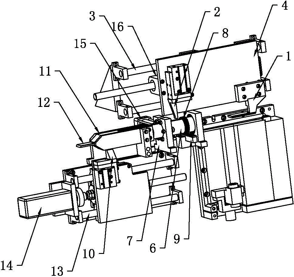
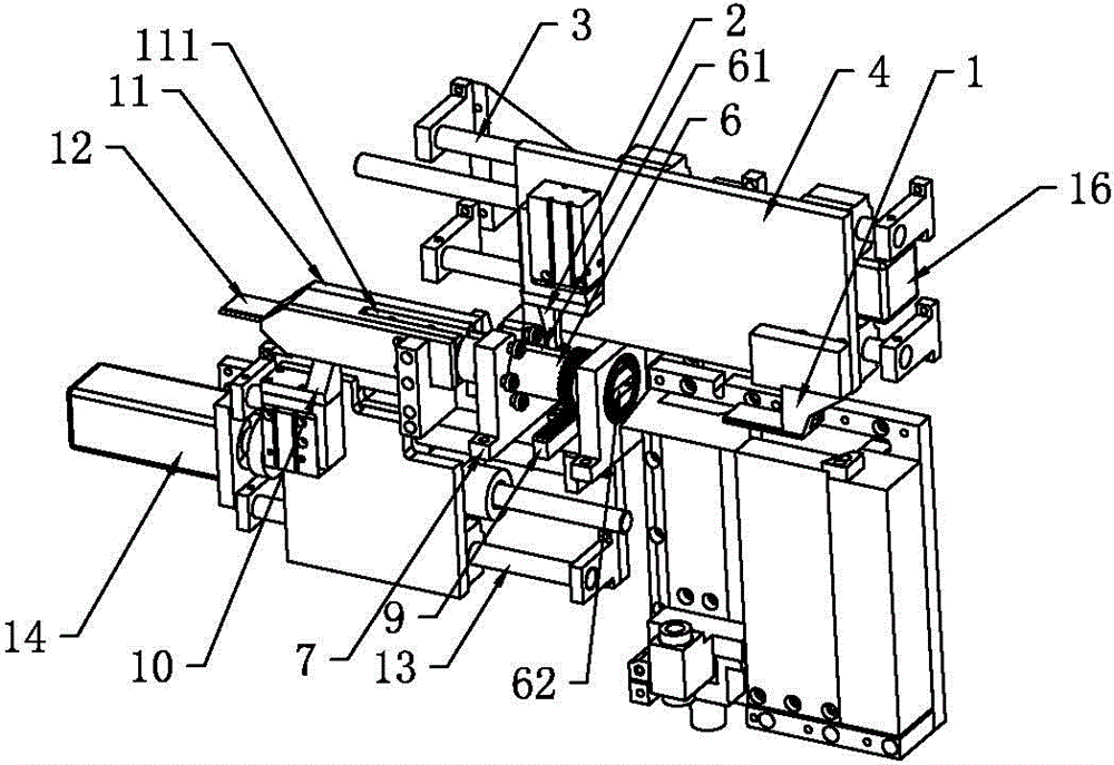
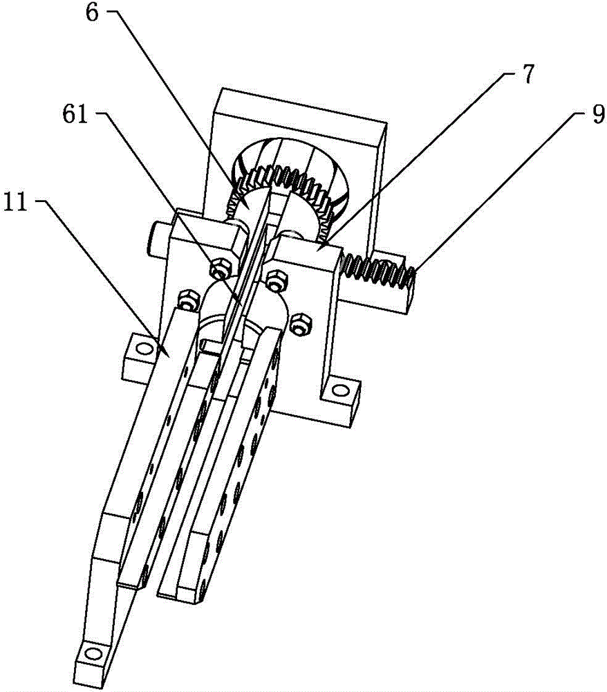
[0035] like Figure 1 to Figure 5 As shown, a method for feeding magnetic tiles in this embodiment includes the following steps,

[0036] Step 1, the first pushing mechanism pushes the single magnetic tile in the stacked magnetic tile stack into the turning cylinder of the turning mechanism;

[0037] Step 2: The Hall sensor senses the magnetoelectric effect caused by the single magnetic tile in the flipping cylinder, and transmits the signal to the controller;

[0038] Step 3, the controller sends an instruction to the rotary driving device of the turning mechanism according to the signal transmitted by the Hall sensor, and the rotating driving device controls the magnetic tile to turn over according to the instruction; specifically: when the instruction issued by the controller to the rotating driving device of the turning mechanism is When overturning, the rotary driving device turns the magnetic tile 180 degrees; when the controller sends an instruction to the rotary drivi...

Embodiment 2

[0045] The difference between a magnetic tile feeding method of this embodiment and Embodiment 1 is that, wherein, the 'next process' of step 4 is provided with a discharge device 11 and a third push mechanism, and the discharge device 11 There is a limit channel 112 narrowed gradually from the feed port to the discharge port, and a discharge guide groove 111 communicated with the limit channel 112, and the discharge guide groove 111 and the plane where the limit channel 112 is located are perpendicular to each other. The feeding port of bit channel 112 is opposite to the discharging port of turning cylinder 6 . The 3rd pushing mechanism comprises the 3rd push rod 10, guide rod 13 and is used to drive the servo motor 14 that the 3rd push rod 10 moves along guide rod 13, and servo motor 14 is connected with controller electric signal, and the 3rd push rod 10 is used for Stretch into the discharge guide groove 111 to push the magnetic tile 12 of the limit channel 112, wherein th...


PUM


Abstract

The invention discloses a magnetic shoe feeding method. A first pushing mechanism is used for pushing a single magnetic shoe in a stacked magnetic shoe pile to a turning mechanism. A Hall sensor senses the magnetoelectric effect caused by the single magnetic shoe, and signals are transmitted to a controller. The controller sends instructions to the turning mechanism according to the signals transmitted by the Hall sensor. The turning mechanism works according to the instructions, so that the purpose that magnetic shoes in different magnetic directions are turned is achieved. Then, a second pushing mechanism pushes the single magnetic shoe in the turning mechanism to a next process. The operation is carried out repeatedly and continuously. The single magnetic shoe in the magnetic shoe pile can be efficiently pushed, and magnetism turning adjusting direction is recognized automatically. Using of magnetic shoes with the same polarity in the next process is convenient.

Description

technical field [0001] The invention relates to the technical field of magnetic tile pasting, in particular to a method for feeding magnetic tiles. Background technique [0002] Magnetic tile usually refers to a kind of tile-shaped magnet mainly used in permanent magnet motors in permanent magnets. Since the magnetic tiles are magnetic, in order to avoid homopolar repulsion when stacking, the polarity directions of two adjacent columns of neatly stacked magnetic tiles should be opposite (such as Figure 5 shown). In the prior art, manual operation is mostly used when pushing a single magnetic tile, and the work efficiency is low, so it is difficult to meet the needs of automatic production and processing. At present, there is almost no special device for automatic magnetic identification of a single magnetic tile in a magnetic tile stack and pushing it to a tile placement machine and other equipment. Although in the field of magnetic tile sorting, the publication number is...

Claims


Application Information

Patent Timeline
Patent Type & Authority Applications(China)
IPC IPC(8): B65G47/248B65G47/82
Inventor 曾繁通向贵宝郑美珠
Owner GUANGZHOU FIRESTEP SELF CONTROL SPECIAL PURPOSE EQUIP
Why Eureka
Try Eureka