
Direct-acting type electric valve
An electric valve, direct-acting technology, applied in the direction of valve details, valve devices, engine components, etc., can solve the problems of reducing the driving force, unable to maintain the coil parts all the time, increasing the size of the motor, etc.
Patent Information
- Authority / Receiving Office
- CN · China
- Current Assignee / Owner
- Publication Date
- 2015-07-22
Smart Images
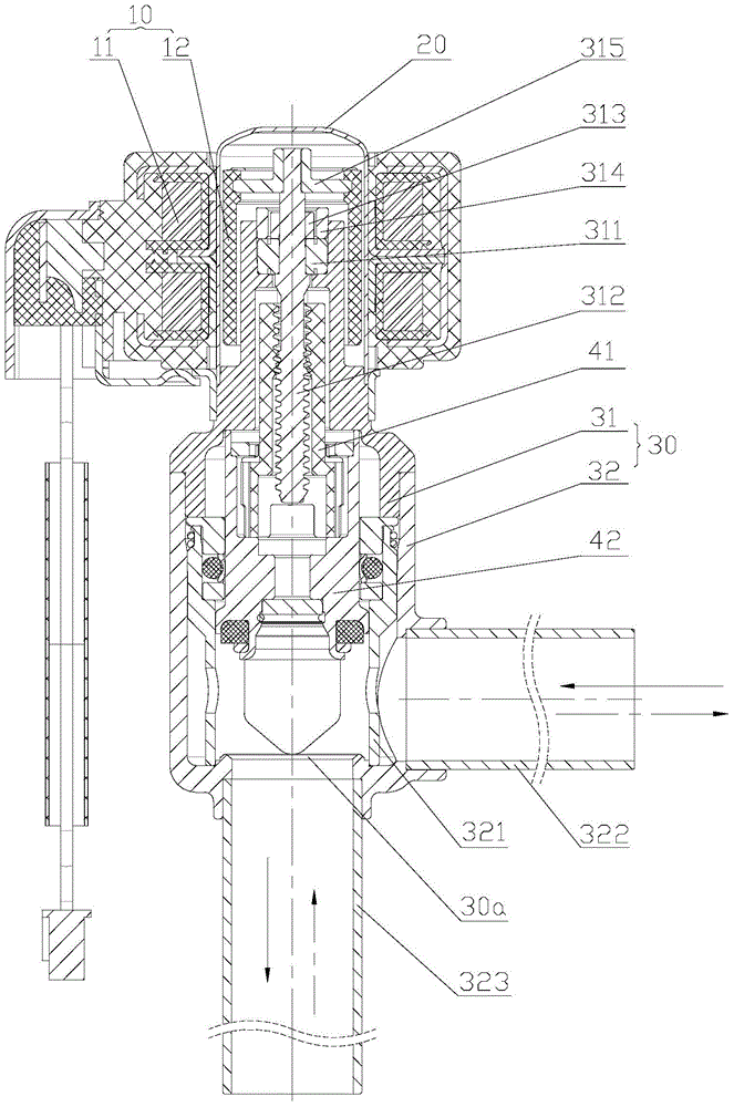
Figure 1 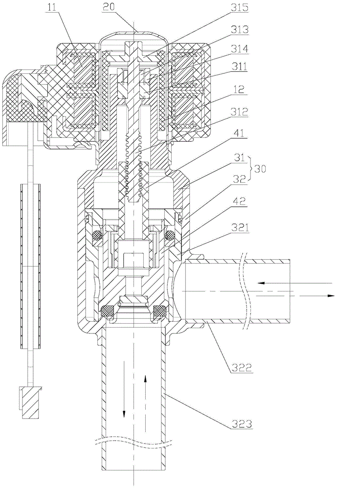
Figure 2 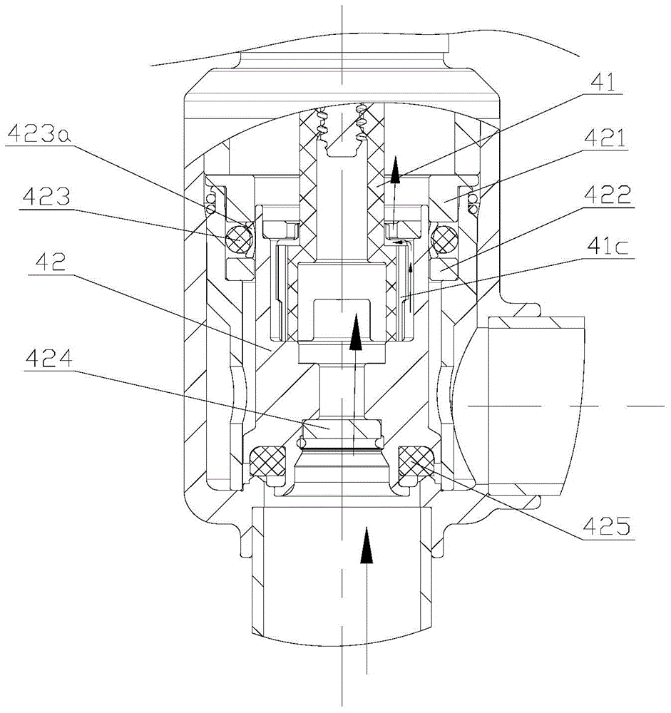
Figure 3
Abstract
Description
technical field
[0001] The invention relates to the technical field of fluid control components, in particular to a direct-acting electric valve. Background technique
[0002] For commercial air conditioners such as multi-split or modular units, one outdoor unit is connected to multiple indoor unit systems. A flow control valve needs to be installed on the refrigerant circuit of each indoor unit to cut off the refrigerant or adjust the flow. The requirement for this flow control valve is to be able to adjust the flow at any opening degree and to operate stably, and because it needs to be installed on the refrigerant circuit of each indoor unit, it is also necessary for the flow control valve to meet the requirements of miniaturization and large capacity.
[0003] At present, the flow control valve mostly adopts a pilot-operated control valve, which uses a motor to drive a pilot valve core, and the main valve core and the pilot valve core open and close the main valve port in...
Examples
Embodiment Construction
[0034] The core of the present invention is to provide a direct-acting electric valve, which can drive the valve core to open and close the large-diameter valve port with a small-sized motor, so as to meet the requirements of miniaturization and large capacity.
[0035] In order to enable those skilled in the art to better understand the solution of the present invention, the present invention will be further described in detail below in conjunction with the accompanying drawings and specific embodiments.
[0036] What needs to be explained here is that the upper and lower localizers involved in this article are based on Figure 1 to Figure 11 The components are located in the drawings and the positions of the components are defined only for the clarity and convenience of expressing the technical solution. It should be understood that the orientation words used herein shall not limit the scope of protection claimed in this application.
[0037] Please refer to Figure 1-2 , ...