
Vertical resistance sensor

A resistance sensor and vertical installation technology, which is applied in the field of vertical resistance sensors, can solve the problems of unreasonable structure setting, poor safety, high assembly tolerance, etc., to improve work stability and use safety, reasonable structure, and reduce deformation loss Effect

Inactive Publication Date: 2015-07-22
FOSHAN CHUANDONG MAGNETOELECTRICITY
View PDF6 Cites 6 Cited by
  • Summary
  • Abstract
  • Description
  • Claims
  • Application Information

AI Technical Summary

Problems solved by technology

[0003] There are many problems in the use of the sensor with this structure. The anti-dry power-off device in the sensor and other fuse protection mechanisms are triggered by the up and down movement of the mounting cup. The anti-dry device and the circuit need frequent power on and off. Action, the anti-dry device and the electrical parts of the circuit are close to each other, which is prone to arcing and surface oxidation, resulting in poor contact and overcurrent damage to the sensor; the working parts in the sensor require high assembly tolerances during assembly, resulting in overall The cost of structural mold opening is high and assembly is difficult; and the internal structure layout of the existing anti-dry burning power-off device is relatively compact, and the unreasonable structure setting leads to poor safety

Method used


Image

  • Vertical resistance sensor
  • Vertical resistance sensor

Examples


Embodiment Construction

[0029] The present invention will be further described below in conjunction with the accompanying drawings.

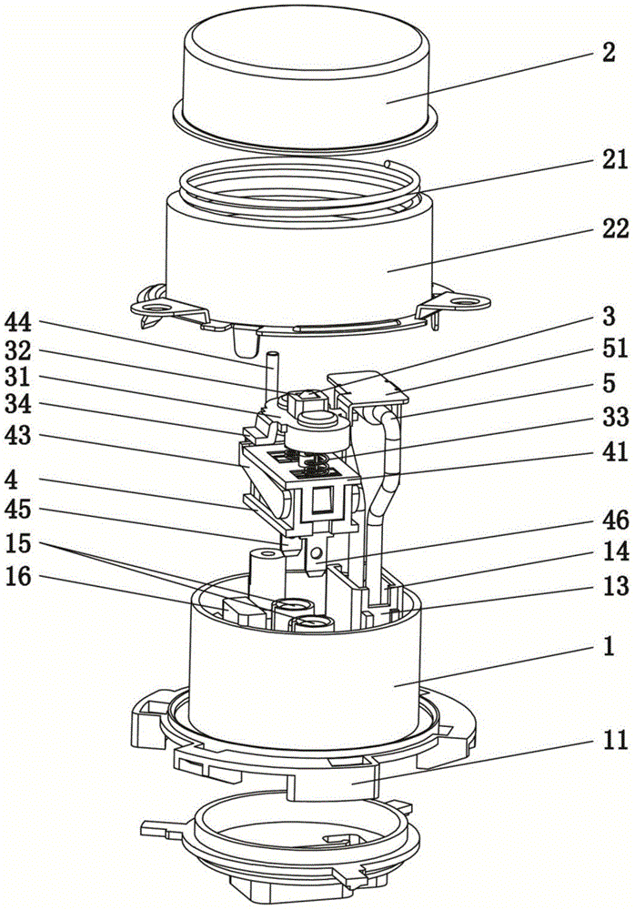
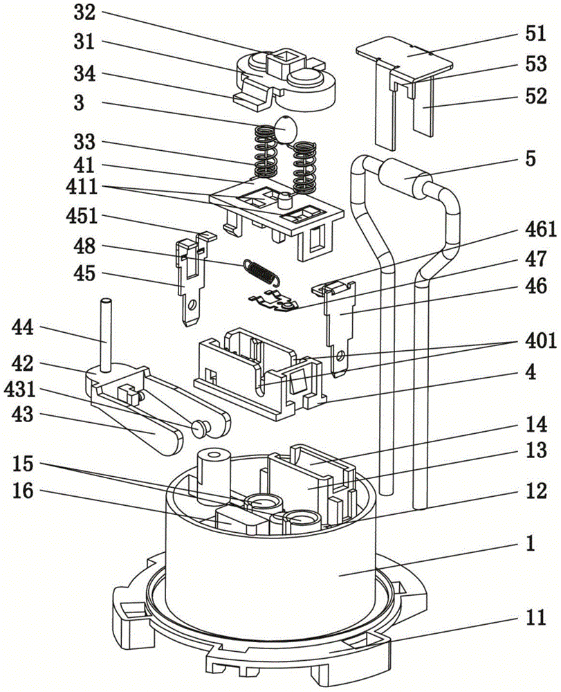
[0030] A vertical resistance sensor according to the present invention comprises a base 1, the upper end of the base 1 is provided with an upper cover 2 which moves up and down relative to it, a fixed plate 12 is arranged horizontally and horizontally inside the base 1, and a fixed plate 12 is provided on the fixed plate 12. The limit mechanism 13 matched with the upper cover 2, the base 1 below the fixed plate 12 is provided with a micro switch, and the micro switch is set in linkage with the upper cover 2; A bracket 31 is provided with a thermistor 3 that cooperates with the upper cover 2 , and both ends of the bracket 31 and the fixing plate 12 are provided with return springs 33 .

[0031] Such as Figure 1-2 As shown, the above-mentioned components are the main structure of the present invention. The upper cover 2 in the initial state is at the highest position, ...


PUM


Abstract

The invention relates to the technical field of temperature control sensor, in particular to a vertical resistance sensor. The vertical resistance sensor comprises a base, the upper end of the base is provided with an upper cover moving up and down relative to the base, a fixing plate is arranged in the base horizontally, a limiting mechanism matched with the upper cover is arranged on the fixing plate, a microswitch is arranged in the base under the fixing plate, and the microswitch and the upper cover are arranged in a linkage manner; a support capable of moving up and down is arranged between the fixing plate and the upper cover, a thermistor matched with the upper cover is arranged on the support, and return springs are arranged at two ends of the support and on the fixing plate. The vertical resistance sensor is reasonable in structure, the upper cover drives an actuating rod to enable the microswitch to send out a pot available signal, the upper cover butts against the thermistor to enable the thermistor to be connected with the microswitch so as to activate overheating power-off protection, and meanwhile a master control circuit is subjected to overcurrent protection by a fuse protector; through the independent acting upper cover, deformation loss of the sensing components in the frequent trigger process is reduced, and working stability and use safety of the sensor are improved.

Description

technical field [0001] The invention relates to the technical field of temperature control sensors, in particular to a vertical resistance sensor. Background technique [0002] Common anti-dry sensors on the market today include a mounting cup, a micro switch and a switch support plate. There is a return spring, and the switch support plate is fixed on the installation base plate. When in use, the installation cup moves down and the micro switch is connected to the heating circuit on the installation base plate. There are thermal components connected in series on the heating circuit. When the installation cup is released, the heating circuit is disconnected. . [0003] There are many problems in the use of the sensor with this structure. The anti-dry power-off device in the sensor and other fuse protection mechanisms are triggered by the up and down movement of the mounting cup. The anti-dry device and the circuit need frequent power on and off. Action, the anti-dry device...

Claims


Application Information

Patent Timeline
IPC IPC(8): G01K7/22
Inventor 刘利龙克文
Owner FOSHAN CHUANDONG MAGNETOELECTRICITY
Learn More