Automatically-locked power supply equipment control system

A technology of power supply equipment and automatic locking, which is applied in the direction of circuits, electrical components, and parts of connecting devices, etc. It can solve the problems of being firm and reliable, unable to realize automatic implementation, and unable to lock the position, so as to achieve the effect of ensuring reliability

Inactive Publication Date: 2015-07-22
邹科寅
View PDF4 Cites 9 Cited by
  • Summary
  • Abstract
  • Description
  • Claims
  • Application Information

AI Technical Summary

Problems solved by technology

However, in the electrical connection of some existing power supply equipment, it cannot guarantee the firm and reliable connection
Or, in power supply equipment that achieves a more reliable electrical connection, it cannot be implemen

Method used


Image

  • Automatically-locked power supply equipment control system
  • Automatically-locked power supply equipment control system
  • Automatically-locked power supply equipment control system

Examples


Embodiment Construction

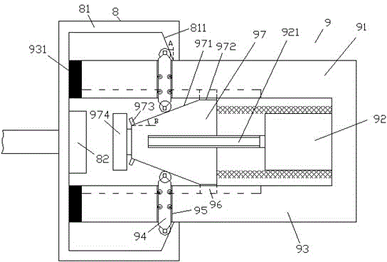
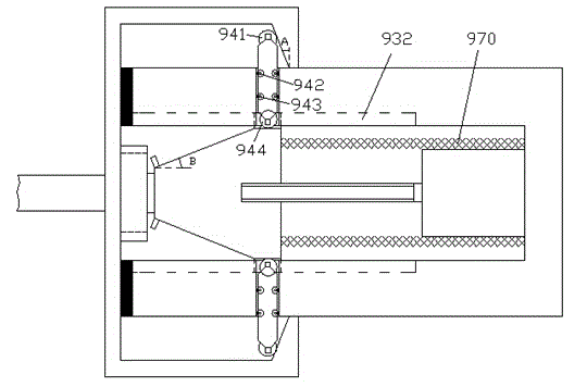
[0011] Combine below Figure 1-3 The present invention is described in detail through the implementation process of specific examples.

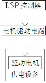
[0012] An automatic locking power supply equipment control system of the present invention includes a DSP controller, a motor drive circuit, and a power supply equipment, the power supply equipment includes a power consumption side component 8 and a power supply side component 9, and the power consumption side component 8 includes The first housing 81 and the first electrical interface 82 disposed inside the first housing 81, the side of the first housing 81 facing the power supply side component 9 is provided with openings and respectively arranged in the openings above and below and has a locking protrusion with a locking slope 811, the power supply side component 9 includes a second housing with an upper side wall 91 and a lower side wall 93, and the second housing is on the upper side wall 91 and the lower side wall There is a cavity bet...


PUM


Abstract

The invention relates to an automatically-locked power supply equipment control system. The power supply equipment control system comprises a DSP (Digital Signal Processor) controller, a motor driving circuit and power supply equipment, wherein the power supply equipment comprises a power utilization side component (8) and a power supply side component (9); the power utilization side component (8) comprises a first shell (81) and a first electric interface (82) which is arranged in the first shell (81); an opening is formed in the side surface, facing to the power supply side component (9), of the first shell (81), and locking bulges with locking oblique surfaces (811) are respectively arranged above and below the opening; the power supply side component (9) comprises a second shell with an upper side wall (91) and a lower side wall (93), a cavity is formed between the upper side wall (91) and the lower side wall (93) of the second shell, and a slidable power supply sliding block (97) which is connected with a power supply through a telescopic lead (970) is arranged in the cavity.

Description

technical field [0001] The invention relates to the field of power supply, in particular to an automatic locking power supply equipment control system. Background technique [0002] Reliable and convenient electrical connection is required between some electrical equipment and power supply equipment. However, in the electrical connection of some existing power supply equipment, it cannot guarantee the firmness and reliability of the connection. Or, in a power supply device that achieves a relatively reliable electrical connection, it cannot be implemented automatically. Moreover, more importantly, it is impossible to guarantee the position locking on the connection plane from the mechanical structure while ensuring the position locking in the direction perpendicular to the connection plane. Contents of the invention [0003] The object of the present invention is to provide an automatic locking power supply equipment control system, which can overcome the above-mentioned...

Claims


Application Information

Patent Timeline
IPC IPC(8): H01R13/639
CPCH01R13/6395
Inventor 邹科寅
Owner 邹科寅
Why Eureka
Try Eureka