Electronic circuit component mounting head

An electronic circuit and mounting head technology, applied to electrical components, electrical components, etc., can solve the problem that it is difficult to detect the contact between the suction nozzle and the object, it is difficult to fully reduce the contact impact, and it is difficult to sensitively control the second lift. Problems with drives, etc.

Active Publication Date: 2017-11-28
FUJI KK
View PDF5 Cites 0 Cited by
  • Summary
  • Abstract
  • Description
  • Claims
  • Application Information

AI Technical Summary

Problems solved by technology

For example, there are problems as follows: Since the nozzle holding shaft, etc., which hold the nozzle for lifting and lowering, are raised and lowered by the second lifting drive device, the mass to be raised and lowered is relatively large. Elastic body, so the abutment of the nozzle and the object cannot be sensitively detected, due to at least one of the above two points, it is difficult to sensitively control the second lifting drive device, and it is difficult to sufficiently reduce the abutment impact

Method used


Image

  • Electronic circuit component mounting head
  • Electronic circuit component mounting head
  • Electronic circuit component mounting head

Examples


Embodiment Construction

[0055]Hereinafter, embodiments of the claimable invention will be described with reference to the drawings. In addition, as an invention that can be claimed, in addition to the following embodiments, it is also possible to implement various changes based on the knowledge of those skilled in the art, as represented by the aspects described in the above-mentioned [Aspects of the Invention] implement.

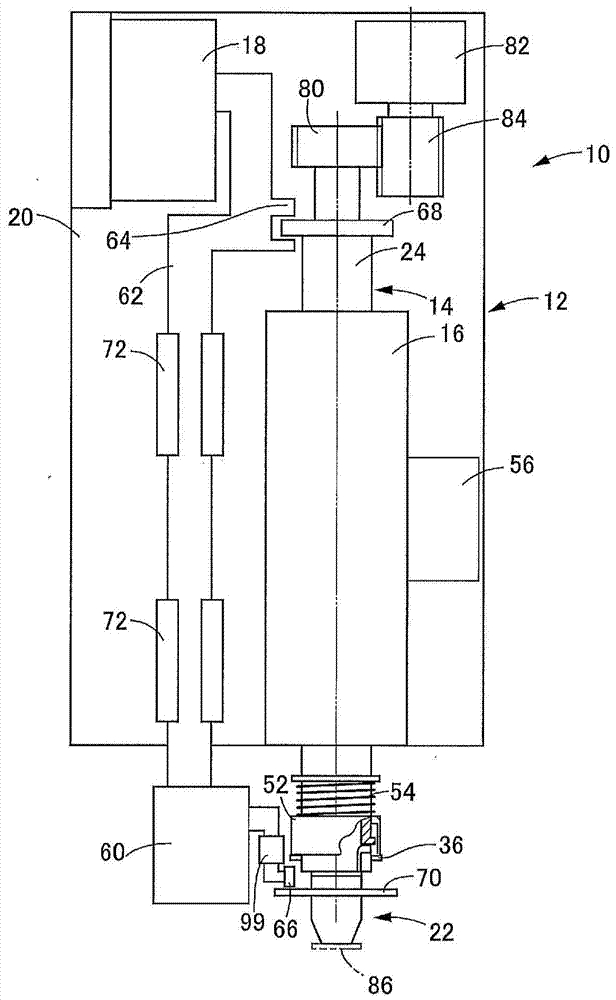
[0056] exist figure 1 An example of the basic structure of the mounting head 10 is shown in . The mounting head 10 has a mounting head body 12, the mounting head body 12 has a first portion 16 and a second portion 20, the first portion 16 allows the lifting of the rotating lifting shaft 14 in a direction parallel to its axis and around its axis. The rotating elevating shaft 14 is held in a rotating state, and the second part 20 holds the first linear motor 18 fixedly. In this embodiment, the first part 16 and the second part 20 are fixed to each other. A suction nozzle 22 serv...


PUM


Abstract

The mounting efficiency of the electronic circuit components on the circuit base material can be kept high, and the damage caused by the abutting impact of the electronic circuit components and the suction nozzle or the circuit base material can be avoided. A rotating lift shaft (14) is held on the head body (12) in a manner capable of rotating and moving up and down, and a suction nozzle (22) is held on the rotating lift shaft (14) in a manner that can be relatively raised and lowered but not relatively rotated. The suction nozzle (22) is forced upward by the force applying unit relative to the rotating lifting shaft (14). In addition, the lift drive member (62) is held on the head main body (12) in a liftable manner, and is raised and lowered by the first linear motor (18). Engage the first engaging portion (64) of the lifting drive member (62) with the rotating lift shaft (14), and on the other hand, make the first engaging portion (64) of the second linear motor (60) held by the lifting drive member (62) The two engaging parts (66) are engaged with the suction nozzle (22), so that the suction nozzle (22) and the rotating lifting shaft (14) are lowered together, and the suction nozzle (22) is relatively rotated against the force of the force applying unit. The lift shaft (14) is lowered, and the component (86) is mounted on the circuit substrate in this state.

Description

technical field [0001] The present invention relates to an electronic circuit component mounting device (hereinafter, unless otherwise required, simply referred to as a component) that holds an electronic circuit component (hereinafter, simply referred to as a component) on a circuit base material by a component holder such as a suction nozzle (hereinafter, unless otherwise required) The electronic circuit component mounting head (hereinafter, if there is no special need, is simply referred to as the mounting head), especially relates to a circuit substrate when the component is relatively fragile and is in contact with the component holder. A mounting head capable of suppressing the impact of contact (hereinafter, simply referred to as the impact of contact unless otherwise required) is easy to break when it is abutted against and can be mounted efficiently while suppressing the impact of contact. Background technique [0002] Patent Document 1 below describes a mounting de...

Claims


Application Information

Patent Timeline
Patent Type & Authority Patents(China)
IPC IPC(8): H05K13/04
CPCH05K13/0413H05K13/0409H05K13/041H05K13/0406Y10T29/53178H05K13/0404
Inventor 河口浩二
Owner FUJI KK
Why Eureka
Try Eureka