Systems and methods for identifying markers

An identifier and identification technology, applied in applications, diagnostic recording/measurement, medical science, etc., can solve the problems of complex slippage, drill breakage, damage, etc., and achieve the effect of reducing the degree of exposure to radiation

Active Publication Date: 2017-10-27
SMITH & NEPHEW PLC
View PDF13 Cites 0 Cited by
  • Summary
  • Abstract
  • Description
  • Claims
  • Application Information

AI Technical Summary

Problems solved by technology

[0011] The inaccuracy of the point of entry also compounds the problem of slipping which is often the case with the rounded end of the drill bit, and thus makes it difficult to set another borehole adjacent to one formed earlier
Inaccurate distal locking can lead to premature failure and breakage of the nail passing through the nail hole, breakage of the screw, or breakage of the drill bit in the bone

Method used


Image

  • Systems and methods for identifying markers
  • Systems and methods for identifying markers
  • Systems and methods for identifying markers

Examples


Embodiment Construction

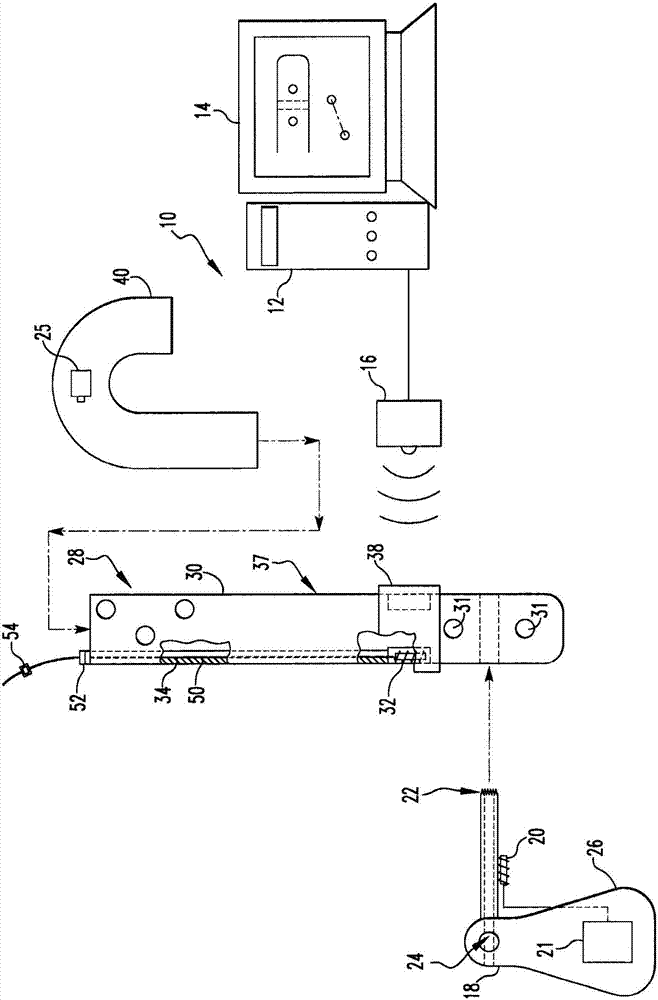
[0084] Referring to the drawings in which like reference numerals indicate like elements, figure 1 A first embodiment of a system 10 for identifying markers is shown. System 10 includes processor 12 , magnetic field generator 16 , marker identifier 18 and orthopedic implant assembly 28 . In some embodiments, the system 10 further includes a monitor 14 electrically connected to the processor 12 and an insertion handle 40 removably attached to the orthopedic implant assembly 28 . processor 12 in figure 1 is shown as a desktop computer, but other types of computing devices could equally be used. As examples, processor 12 may be a desktop computer, laptop computer, personal digital assistant (PDA), mobile handheld device, or a dedicated device. In the illustrated embodiment, the magnetic field generator is a device available from the following suppliers: Ascension Technology Corporation of 107 Catamount Drive, Milton Vermont, U.S.A.; Northern Digital Inc. of 103 Randall Drive, ...


PUM


Abstract

The present invention discloses a system (1010, 1110) for identifying markers. The system includes a field generator (1016, 1116) for generating a magnetic field, an orthopedic implant (1030, 1130) positioned within the magnetic field, the implant having at least one marker (1028, 1128), Removable detector (1029, 1129) with first magnetic sensor (1026, 1126), marker identifier (1016, 1116) with second magnetic sensor (1020, 1120), and processor (1012, 1112) , the processor for comparing sensor data from the first sensor and the second sensor and using a set distance to calculate a position of the marker identifier relative to the at least one marker. The invention enables blind targeting of one or more markers.

Description

[0001] This application is a divisional application, the application number of the original application is 200880128908.3, the application date is October 28, 2010, and the title of the invention is "system and method for identifying marks". [0002] Cross References to Related Applications [0003] This application claims the benefit of PCT International Patent Application No. PCT / US2008 / 55300 filed February 29, 2008. The entire disclosure of this application is hereby incorporated by reference. [0004] Statement Involving Federally Sponsored Research or Development [0005] Not applicable. [0006] appendix [0007] Not applicable. technical field [0008] Embodiments of the present invention relate generally to orthopedic implants, and more particularly, embodiments of the present invention relate to identifying blind landmarks on orthopedic implants. Background technique [0009] The use of interlocking femoral screws has greatly expanded the scope of intramedullar...

Claims


Application Information

Patent Timeline
Patent Type & Authority Patents(China)
IPC IPC(8): A61B17/17A61B17/72A61B90/90
CPCA61B5/064A61B17/1707A61B17/1725A61B17/72A61B2090/3958A61B2090/397
Inventor J·K·雷恩斯N·S·里基G·E·奥斯丁H·B·费伯N·K·格鲁辛T·施韦利W·M·里奇S·W·詹纳C·C·赫奥蒂斯
Owner SMITH & NEPHEW PLC
Why Eureka
Try Eureka