High-temperature moving spherical rearview mirror glass suction device

A suction device and rear-view mirror technology, applied in transportation and packaging, manual conveying devices, furnaces, etc., can solve the problems of scrapped spherical glass, falling gaps in contact positions, affecting the air tightness of vacuum adsorption, etc., to ensure quality. and stability, avoid contusion, avoid the effect of defective products

Inactive Publication Date: 2015-07-29
DONGGUAN XINTENG ROBOT TECH
View PDF5 Cites 2 Cited by
  • Summary
  • Abstract
  • Description
  • Claims
  • Application Information

AI Technical Summary

Problems solved by technology

In the prior art, in this process, a layer of heat-insulating glue and high-temperature-resistant tape is placed on the traditional vacuum suction cup by manual handling, and then a layer of fine copper wire mesh is put on at the end. This layer of fine copper wire mesh is directly exposed to high temperature The spherical structure of the glass contact, relying on manual experience to perceive the proper gravity of the vacuum suction cup to adsorb on the surface of the spherical glass, if the force of the vacuum suction cup falling and the adsorption contact with the spherical glass is too light, there will be a gap in the contact position and fall, and if it is too heavy, it will There are traces on the surface of the spherical glass, causing the spherical glass to be scrapped; in addition, the surface of the spherical glass is concave, and there is a gap where the vacuum suction cup contacts the concave glass, and the gap will directly affect the airtightness of the vacuum adsorption, resulting in glass Poor adsorption stability

Method used


Image

  • High-temperature moving spherical rearview mirror glass suction device
  • High-temperature moving spherical rearview mirror glass suction device

Examples


Embodiment Construction

[0019] The present invention will be described in detail below in conjunction with the accompanying drawings.

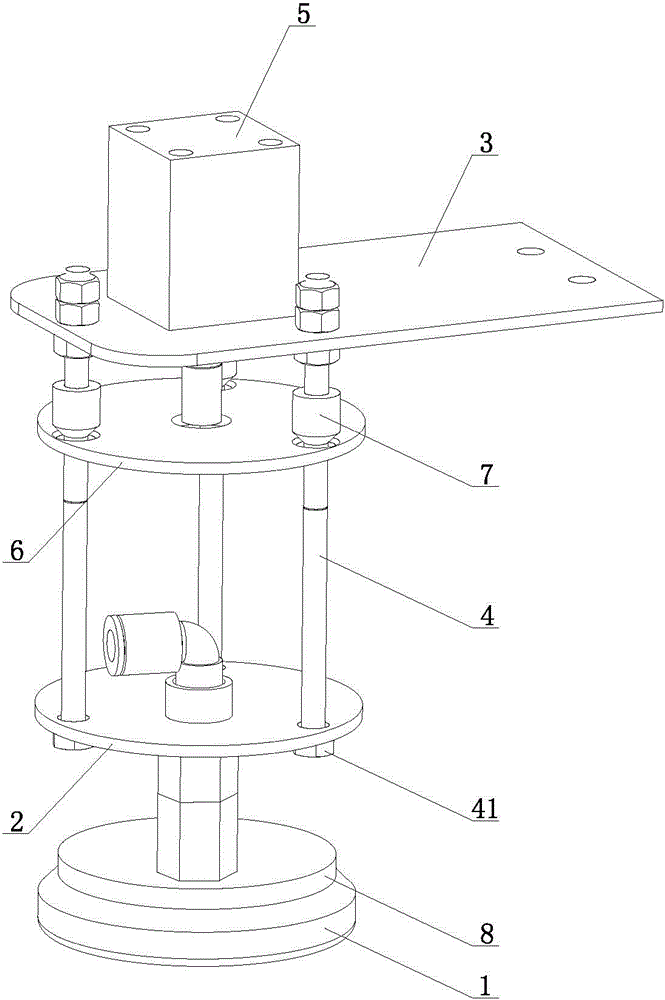
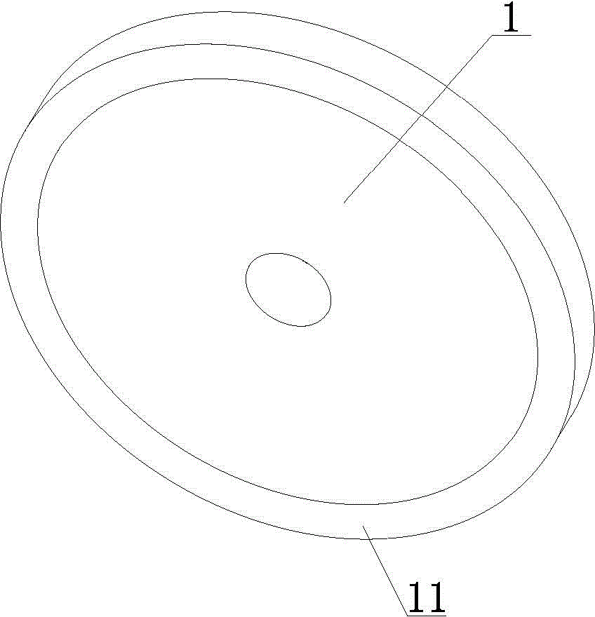
[0020] Such as Figure 1~2 As shown, a kind of high-temperature sports spherical rearview mirror glass suction device of the present invention comprises a floating control device and a metal vacuum chuck 1, and the floating control device includes a lower floating plate 2, an upper fixed plate 3 and a floating connecting rod 4, and the lower floating plate 2. A lower floating hole with an aperture larger than the diameter of the floating connecting rod 4 is provided. The bottom end of the floating connecting rod 4 is provided with a round table 41, and the top end of the floating connecting rod 4 passes through the lower floating hole and is non-tightly connected with the upper fixing plate 3. , the lower floating plate 2 abuts against the round platform 41 , and the metal vacuum chuck 1 is located under the lower floating plate 2 and connected with the lower floatin...


PUM


Abstract

The invention relates to the technical field of glass suction device, in particular to a high-temperature moving spherical rearview mirror glass suction device. The high-temperature moving spherical rearview mirror glass suction device comprises a floating control device and a metal vacuum cup, wherein the floating control device comprises a lower floating plate, an upper floating plate and a floating connection rod. The lower floating plate is provided with a lower floating hole with the hole diameter greater than the rod diameter of the floating connection rod, a circular table is arranged at the bottom end of the floating connection rod, the top end of the floating connection rod penetrates through the lower floating hole to be connected with an upper fixing plate, the lower floating plate is in butting connection with the circular table, and the metal vacuum cup is located under the lower floating plate and is connected with the lower floating plate. When the high-temperature moving spherical rearview mirror glass suction device conducts suction on high-temperature spherical glass in a moving state, it can be ensured that the surface of the spherical glass is not damaged and scratched, defective products can be avoided, dropping and glass surface impressions caused by shake in the suction process of the spherical glass can be avoided, and suction quality and stability can be ensured.

Description

technical field [0001] The invention relates to the technical field of glass absorbing devices, in particular to a glass absorbing device for a high-temperature sports spherical rearview mirror. Background technique [0002] When the driver is driving in the car, he can only see the front and both sides through his eyes, and he can only observe the rear situation through the rearview mirrors on both sides of the car. The rearview mirror is also called the "third eye" by the driver. The importance of mirrors for drivers. Rearview mirrors generally have a spherical structure. During the manufacturing process, glass with a planar structure is baked to form a glass with a spherical structure. In this production process, it involves a process of absorbing the spherical glass that is under high temperature and moving on the production line. In the prior art, in this process, a layer of heat-insulating glue and high-temperature-resistant tape is placed on the traditional vacu...

Claims


Application Information

Patent Timeline
IPC IPC(8): B65G47/91B65G7/12B65G49/05B65G47/22
Inventor 韩文召房豪欧阳于超陈炼
Owner DONGGUAN XINTENG ROBOT TECH
Why Eureka
Try Eureka