A sludge drying device

A sludge drying and drying technology, which is applied in the direction of sludge treatment through temperature control, dehydration/drying/concentrated sludge treatment, etc., can solve the problems of low drying power, low drying humidity of materials, and large energy consumption, etc., to achieve Ease of production and maintenance, low follow-up processing costs, and low equipment failure rate

Active Publication Date: 2016-08-31
JIANGSU NENGZHENG ENVIRONMENTAL PROTECTION TECH CO LTD
View PDF7 Cites 0 Cited by
  • Summary
  • Abstract
  • Description
  • Claims
  • Application Information

AI Technical Summary

Problems solved by technology

[0002] At present, there are many methods for harmless treatment of sludge, but first of all, the sludge needs to be dried. Traditional sludge drying equipment such as paddle type and horizontal disc type, but because the material is deposited in the drying chamber , steam accumulation, poor air permeability, extremely small difference in drying humidity of materials, low drying power, and steam cannot quickly leave the carrier. 1. High extrusion strength, poor equipment durability, high driving power and high energy consumption; while fluidized bed, rotary kiln, medium temperature zone type, all rely on hot air to take away steam, the amount of dust in the process is large, and the safety is low At the same time, a large amount of exhaust gas requires high treatment costs. Due to the stickiness of the sludge, it is easy to cause perforated dead beds, fan failures, etc.

Method used


Image

  • A sludge drying device
  • A sludge drying device
  • A sludge drying device

Examples


Embodiment Construction

[0026] The present invention will be further described below in conjunction with the accompanying drawings.

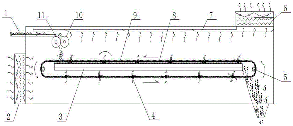
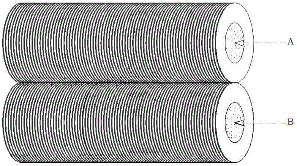
[0027] Such as figure 1 As shown, the sludge drying device includes a squeeze roller 10 installed above the drying heating plate 3 and connected to the sludge conveyor 1;

[0028] A chain 8 is installed around the outside of the drying heating plate 3;

[0029] The two ends of described chain 8 are driven by driving sprocket 5;

[0030] A gear bar 9 is arranged between the upper part of the drying heating plate 3 and the chain 8;

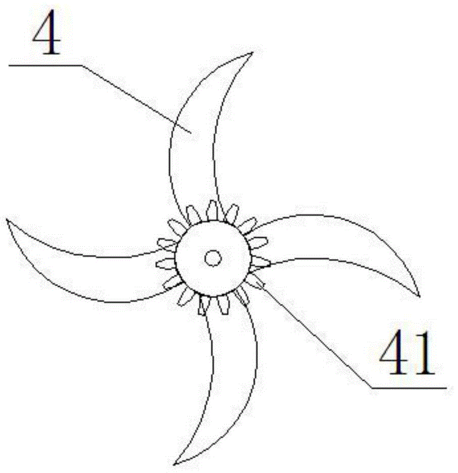
[0031] Rake knives 4 are evenly distributed on the chain 8;

[0032] A rake driving gear 41 is arranged at the axis of the rake 4 and meshes with the gear bar 9 .

[0033] The working process of the sludge drying device is as follows:

[0034] Such as figure 1 As shown, the sludge conveyor 1 transports the sludge to the squeezing roller 10, and the squeezing roller 10 squeezes the sludge into noodles and then falls to the drying heatin...


PUM


Abstract

The invention discloses a sludge drying device, and belongs to the technical field of sludge drying. The sludge drying device comprises a kneading roller (10) mounted above a drying heating tray (3) and connected with a sludge conveyor (1), wherein the drying heating tray is encircled by a chain (8); the two ends of the chain are driven by drive sprockets (5); a gear rack (9) is arranged between the upper part of the drying heating tray and the chain; harrow cutters (4) are uniformly distributed on the chain. The sludge drying device is high in porosity, large in superficial area of sludge particles, light in ton proportion, strong in breathability, high in humidity difference value, powerful in drying power, and quick in rate of evaporation; the sludge material is longitudinally shifted and conveyed, and the cutting force breaks the adhesion of the sludge, so that the sludge cannot generate a snowball effect; the sludge drying device is simpler by modularization, convenient to transport, low in failure rate, and convenient to produce and maintain, and has the advantage that phenomena such as dust caused by falling are avoided; in the drying process, the back mixing is not required, the exhausted air quantity is low, and the follow-up handling expense is low.

Description

technical field [0001] The invention relates to a drying device, in particular to a sludge drying device, which belongs to the technical field of sludge drying. Background technique [0002] At present, there are many methods for harmless treatment of sludge, but first of all, the sludge needs to be dried. Traditional sludge drying equipment such as paddle type and horizontal disc type, but because the material is deposited in the drying chamber , steam accumulation, poor air permeability, extremely small difference in drying humidity of materials, low drying power, and steam cannot quickly leave the carrier. 1. High extrusion strength, poor equipment durability, high driving power and high energy consumption; while fluidized bed, rotary kiln, medium temperature zone type, all rely on hot air to take away steam, the amount of dust in the process is large, and the safety is low , At the same time, a large amount of exhaust gas requires high treatment costs. Due to the sticki...

Claims


Application Information

Patent Timeline
Patent Type & Authority Patents(China)
IPC IPC(8): C02F11/12C02F11/18
CPCC02F11/12
Inventor 朱姜龙
Owner JIANGSU NENGZHENG ENVIRONMENTAL PROTECTION TECH CO LTD
Why Eureka
Try Eureka