An anchor bolt expansion sleeve and its manufacturing method

A manufacturing method and petal technology, which are applied in the manufacture of anchor bolt expansion sleeves and the structural field of metal stamping sheets used in manufacturing expansion sleeves, can solve the problems of falling plates, unreliable push fit, increase manufacturing costs, etc., to prevent The effect of false expansion

Active Publication Date: 2016-08-24
HANGZHOU STAN NEW MATERIALS TECH CO LTD
View PDF4 Cites 0 Cited by
  • Summary
  • Abstract
  • Description
  • Claims
  • Application Information

AI Technical Summary

Problems solved by technology

[0004] Regarding the manufacturing process of the expansion sleeve 2, some are made by cutting pipe fittings, but the manufacturing process is complicated and the cost is high; there are also metal sheets that are punched to form cylinders, and the structure of the metal sheets is as follows: Image 6 As shown, the metal sheet is petal-shaped, with a circular central hole in the middle of the sheet, and the stamping direction is along the axis of the central hole. After stamping, the petals form a load tongue, and the original circular central hole forms the upper end of the cylinder.
[0005] However, due to being extruded during the stamping process, unevenness will appear on the top of the base section 2-1, such as image 3 , Figure 4 , Figure 5 As shown, the push fit between the expansion sleeve 2 and the sleeve 1 of this structure is unreliable, and the load tongue 2-2 cannot achieve balanced expansion. The bolt nut is loose, there is a hidden danger of the plate falling
If the top of the expansion sleeve 2 is further processed, such as milling the end face, or lathe cutting to form a plane, the manufacturing cost will be increased

Method used


Image

  • An anchor bolt expansion sleeve and its manufacturing method
  • An anchor bolt expansion sleeve and its manufacturing method
  • An anchor bolt expansion sleeve and its manufacturing method

Examples


Embodiment Construction

[0033] In order to further explain the technical means and functions adopted by the present invention to achieve the intended technical purpose, the structure, features and functions of the present invention will be described in detail below in conjunction with the accompanying drawings and preferred embodiments.

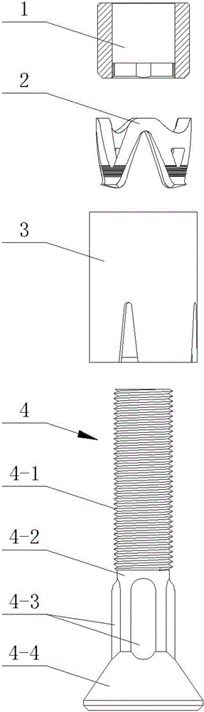
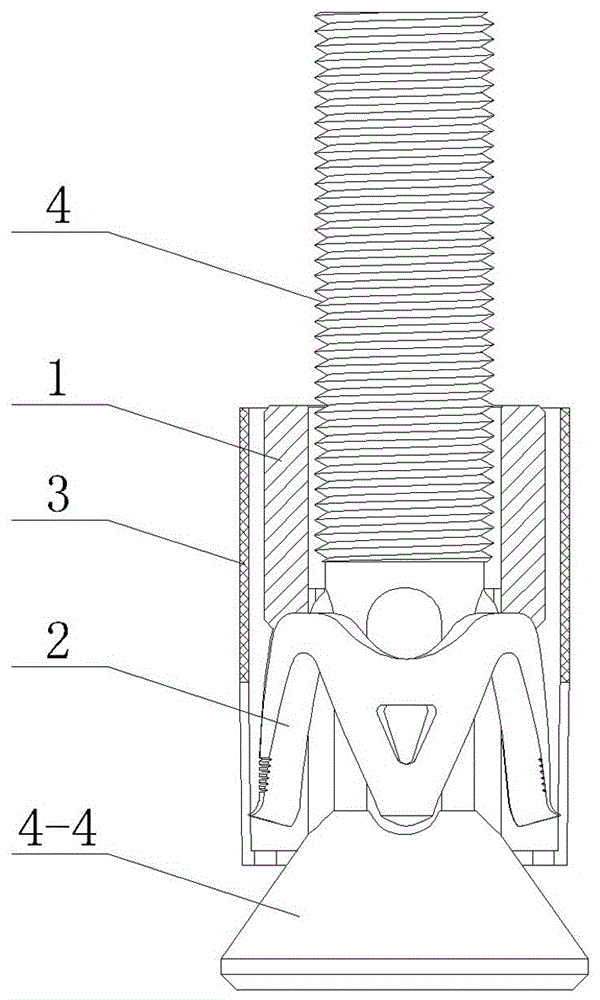
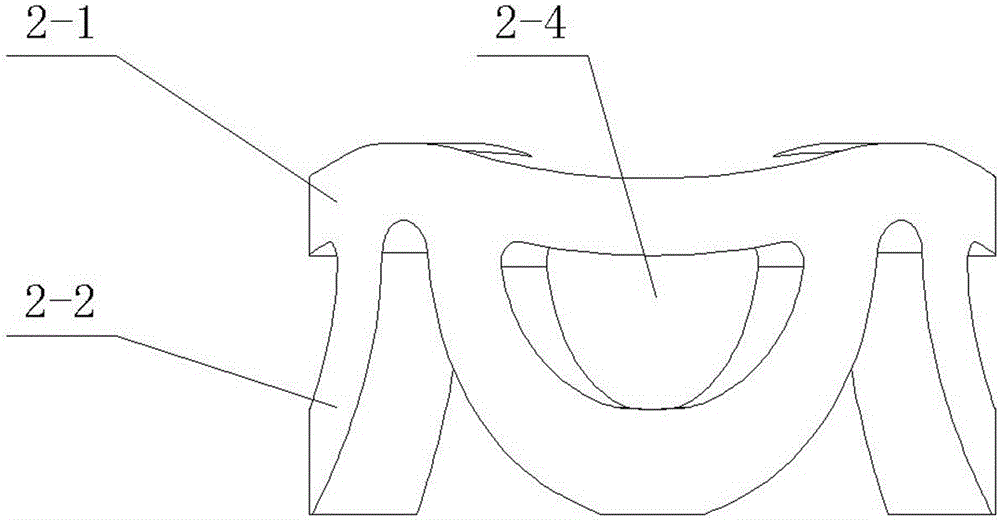
[0034] A method of manufacturing an anchor bolt expansion sleeve described in this embodiment, firstly, a sheet metal body is made, such as Figure 10 , Figure 11 As shown, the sheet body is petal-shaped, including several petal bodies, the number of petal bodies is equal to the number of load tongues of the expansion sleeve, and a circular arc transition is adopted between adjacent petal bodies; a polygonal central hole 2-5 is set in the middle of the sheet body , the top corners of the polygonal central hole 2-5 are set as rounded corners; secondly, the metal sheet body is made into an expansion sleeve through a stamping process, and the stamping direction is alo...


PUM


Abstract

A manufacturing method of an anchor bolt expanding sleeve, the method comprising: manufacturing a metal sheet member, the sheet member having a shape of a flower with petals and comprising several petal members, wherein the number of the petal members is equal to the number of load tongues (2-2) of the expanding sleeve (2), and a curved transition is adopted between neighboring petal members; arranging a polygonal central hole (2-5) at a middle portion of the sheet member, wherein the number of edges of the polygonal central hole (2-5) is equal to the number of the load tongues (2-2), the locations of the edges of the polygonal central hole (2-5) correspond to the locations of the load tongues (2-2), and vertexes of the polygonal central hole (2-5) are configured to be rounded corners; and manufacturing the metal sheet member into the expanding sleeve via a punching process, wherein a punching direction is a thickness direction of the sheet member. Further provided is an expanding sheet comprising a base section (2-1) and several load tongues (2-2), wherein the base section (2-1) and the load tongues (2-2) are integrally manufactured, respective load tongues (2-2) are provided with a rectangular process hole (2-4) thereon, and vertexes of the rectangular process hole (2-4) are configured to be rounded corners. A top end of a base section of the expanding sleeve has a plane shape, and a rear bolt is securely installed.

Description

technical field [0001] The invention relates to a method for manufacturing an anchor bolt expansion sleeve, in particular to the structure of a metal stamping sheet used in manufacturing the expansion sleeve. The invention also relates to the anchor expansion sheath produced by this manufacturing method. Background technique [0002] The back bolt used in the curtain wall of the external envelope of the building, the structure is as follows figure 1 , figure 2 As shown, it includes an anchor rod 4 , an expansion sleeve 2 , a sleeve 1 for pushing the expansion sleeve 2 , and a flexible sleeve 3 . [0003] The expansion sleeve 2 has various structures, one of which is as image 3 , Figure 4 , Figure 5 As shown, it is composed of a base section 2-1 and several load tongues 2-2. The load tongue 2-2 is in the shape of a tongue or a curved tongue; the base section 2-1 and the load tongue 2-2 are integrally made, and the load tongue 2-2 is formed in one piece. The surface ...

Claims


Application Information

Patent Timeline
Patent Type & Authority Patents(China)
IPC IPC(8): E04F13/24E04B2/88
CPCE04B2/88E04F13/24
Inventor 徐跃华徐洁媛张清华周桂云
Owner HANGZHOU STAN NEW MATERIALS TECH CO LTD
Why Eureka
Try Eureka