Multi-plate type automatic foldable stage and controlling method of multi-plate type automatic foldable stage
A control method and stage technology, applied in theaters and other directions, can solve the problems of rigid structure, no disassembly or movement of the stage, etc., and achieve the effect of ensuring coordination, simple operation, and rational use of site resources
- Summary
- Abstract
- Description
- Claims
- Application Information
AI Technical Summary
Problems solved by technology
Method used
Image

Examples
Embodiment Construction
[0028] The present invention is described in detail below in conjunction with accompanying drawing and embodiment, through the following detailed description, can understand the present invention more completely and better and easily know wherein many accompanying advantages, but the accompanying drawing described here is used to provide the present invention A further understanding of the invention constitutes a part of the present application, and the exemplary embodiments of the present invention and their descriptions are used to explain the present invention, and do not constitute an improper limitation of the present invention.
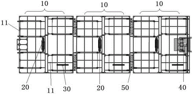
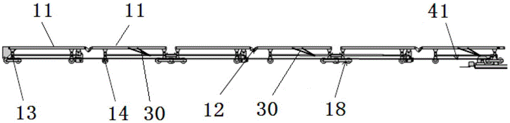
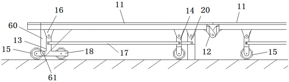
[0029] Such as Figure 1 to Figure 5 As shown, the present invention provides a multi-plate type automatic folding stage, which includes three groups of stages 10, three lifting mechanisms 20, three electric push rod mechanisms 30, a winch 40, a push-pull device and a controller, the first Group stage 10 and third group stage 10 are located at b...
PUM
 Abstract
Description
Claims
Application Information
PatSnap Eureka turns technology decisions into work you can execute. Powered by our Innovation Knowledge Graph, it runs expert workflows across engineering, life sciences, materials and intellectual property. Get your review-ready output in minutes.


