
Dual-motor starting gear speed-reducing wheel type energy storage device

An energy storage device and gear deceleration technology, which can be used in electromechanical devices, electric components, control mechanical energy, etc., and can solve the problem of insignificant energy saving effect.

Inactive Publication Date: 2015-07-29
WEILE ENERGY TECH BEIJING CO LTD
View PDF0 Cites 0 Cited by
  • Summary
  • Abstract
  • Description
  • Claims
  • Application Information

AI Technical Summary

Problems solved by technology

[0002] The beam pumping unit currently used is generally equipped with a weight on the crank. This counterweight method cannot make the pumping unit run smoothly, and the energy saving effect is not significant

Method used


Image

  • Dual-motor starting gear speed-reducing wheel type energy storage device
  • Dual-motor starting gear speed-reducing wheel type energy storage device

Examples


Embodiment 1

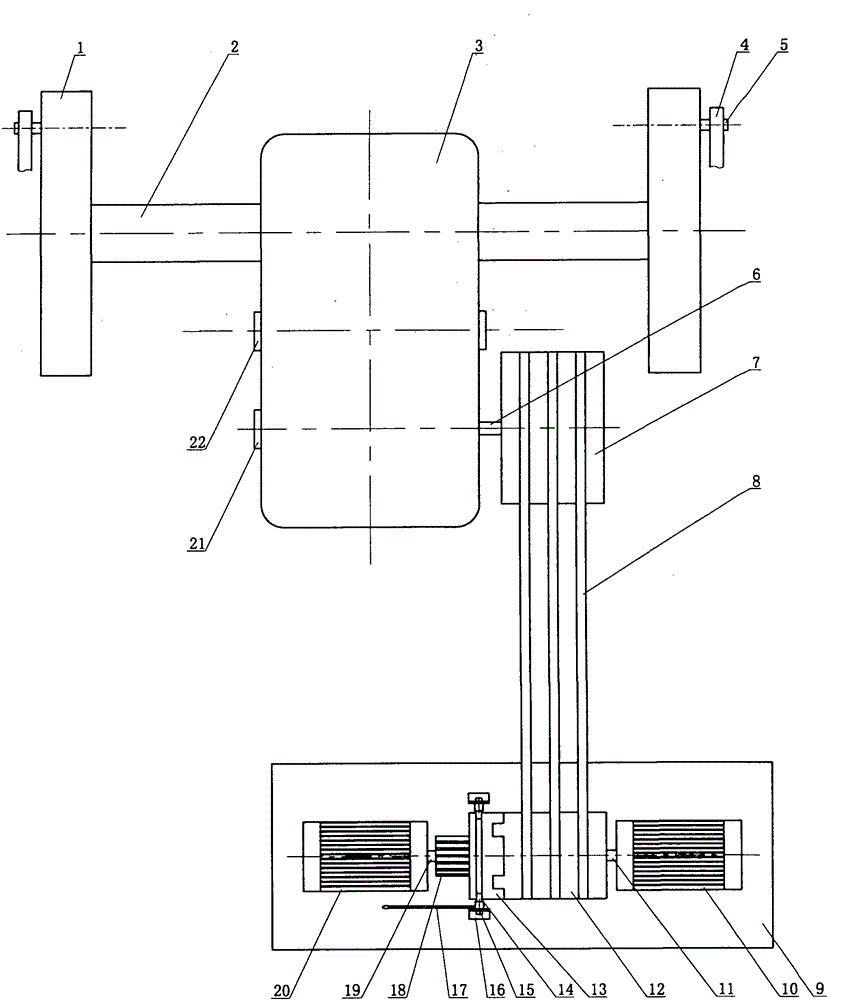
[0013] Such as figure 1 The present embodiment shown includes an output shaft wheel 1, an output shaft 2, a gear reduction box 3, a connecting rod 4, a connecting rod shaft 5, an input shaft 6, an input shaft pulley 7, a belt 8, a motor base 9, and a working motor 10 , working motor shaft 11, motor pulley 12, tooth insert 13, shift fork 14, shift fork shaft 15, shift fork base 16, pull rod 17, spline shaft 18, start motor shaft 19, start motor 20, input shaft bearing cover 21 And intermediate shaft bearing cover 22 etc. The output shaft wheel 1 is installed on the output shaft 2 of the gear reduction box 3, the connecting rod shaft 5 connects the connecting rod 4 and the output shaft wheel 1, and the input shaft pulley 7 is installed on the input shaft 6 of the gear reduction box 3. Working motor 10 is installed on the motor base 9, motor pulley 12 is installed on the working motor shaft 11, and the outside of motor pulley 12 has teeth, so that with tooth socket 13 interlocki...

Embodiment 2

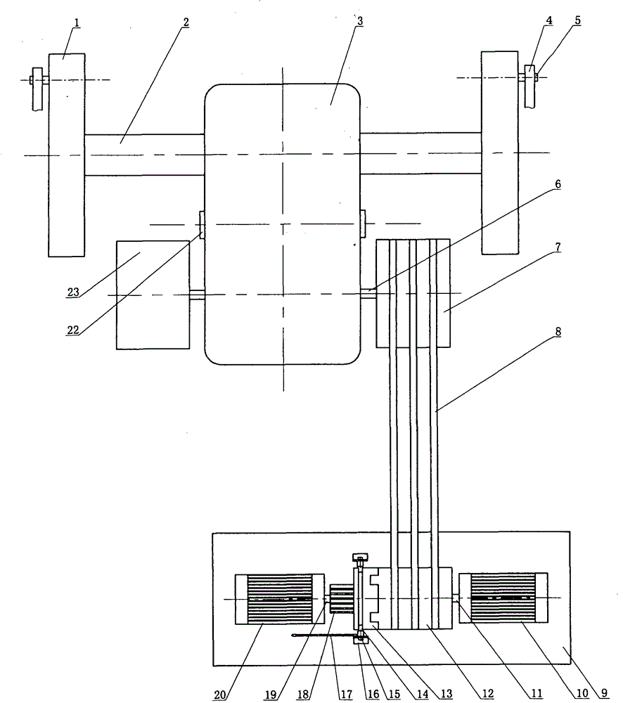
[0015] Such as figure 2 The present embodiment shown includes an output shaft wheel 1, an output shaft 2, a gear reduction box 3, a connecting rod 4, a connecting rod shaft 5, an input shaft 6, an input shaft pulley 7, a belt 8, a motor base 9, and a working motor 10 , working motor shaft 11, motor pulley 12, tooth insert 13, shift fork 14, shift fork shaft 15, shift fork base 16, pull rod 17, spline shaft 18, start motor shaft 19, start motor 20, intermediate shaft bearing cover 22 And input shaft wheel 23 etc. An output shaft wheel 1 is installed on the output shaft 2 of the gear reduction box 3, and the connecting rod shaft 5 connects the connecting rod 4 and the output shaft wheel 1 together. An input shaft pulley 7 is installed at one end of the input shaft 6 of the gear reduction box 3. One end is equipped with input shaft wheel 23. Working motor 10 is installed on the motor base 9, motor pulley 12 is installed on the working motor shaft 11, and the outside of motor p...


PUM


Abstract

The invention relates to a dual-motor starting gear speed-reducing wheel type energy storage device, in particular to a wheel type energy storage device suitable for beam pumping unit energy conservation. The dual-motor starting gear speed-reducing wheel type energy storage device comprises output shaft wheels 1, an output shaft 2, a speed reduction gear box 3, connecting rods 4, connecting rod shafts 5, an input shaft 6, input shaft belt wheels 7, belts 8, a motor base 9, a working motor 10, a working motor shaft 11, motor belt wheels 12, a jaw 13, a shifting fork 14, a shifting fork shaft 15, a shifting fork base 16, a pull rod 17, a spline shaft 18, a starting motor shaft 19, a starting motor 20, an input shaft bearing cover 21, intermediate shaft bearing covers 22, an input shaft wheel 23 and the like. The dual-motor starting gear speed-reducing wheel type energy storage device has the advantages that when the oil sucker rod does up and down reciprocating motion and the walking beam load of the oil pumping unit is imbalanced, due to the adopting of the wheel type energy storage device, the oil pumping unit operates stably, the conservation of energy resources is facilitated, and the motors are protected.

Description

technical field [0001] The invention relates to a double-motor starting gear reduction wheel type energy storage device, in particular to a wheel type energy storage device suitable for energy saving of beam pumping units. Background technique [0002] The beam pumping unit currently used is generally equipped with a weight on the crank. This counterweight method cannot make the pumping unit run smoothly, and the energy-saving effect is not significant. Contents of the invention [0003] The purpose of the present invention is to design a double-motor starting gear reduction wheel type energy storage device to increase the stability of the pumping unit's operation and improve the energy saving effect of the pumping unit. [0004] The present invention comprises output shaft wheel 1, output shaft 2, gear reduction box 3, connecting rod 4, connecting rod shaft 5, input shaft 6, input shaft pulley 7, belt 8, motor base 9, working motor 10, working motor shaft 11 , motor pull...

Claims


Application Information

Patent Timeline
IPC IPC(8): H02K7/10
CPCH02K7/116
Inventor 刘玉玺刘蕾刘伟
Owner WEILE ENERGY TECH BEIJING CO LTD
Learn More