mri compatible lead coil

A wire and coil technology used in the field of implantable medical devices

Inactive Publication Date: 2016-11-16
CARDIAC PACEMAKERS INC
View PDF4 Cites 0 Cited by
  • Summary
  • Abstract
  • Description
  • Claims
  • Application Information

AI Technical Summary

Problems solved by technology

Exposure to magnetic fields can also cause unwanted voltages on wires

Method used


Image

  • mri compatible lead coil
  • mri compatible lead coil
  • mri compatible lead coil

Examples


Embodiment Construction

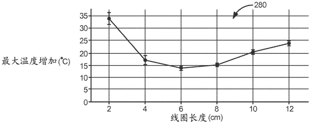
[0037] Magnetic resonance imaging is a useful tool for non-invasive visualization and analysis of a patient's internal anatomy. However, radio frequency (RF) fields generated in the MRI environment can induce electrical currents in conductive elements such as conductors of medical electrical leads of implantable pulse generators or other medical devices. The electrical current may be induced by an RF field in an elongated conductor (eg, a cable) along an insulated segment of the wire and then conducted to a non-insulated element of the wire (eg, a stimulation coil or electrode) that contacts patient tissue. The induced MRI energy may then be converted to thermal energy when dissipated to the patient's tissue. If the temperature is high enough, the heating caused by the dissipated energy can be detrimental to the tissue adjacent to the wire. Minimizing peak heating associated with induced RF energy may allow the lead to be used safely in an MRI environment. Among other things...


PUM


Abstract

Various embodiments relate to leads with low peak MRI heating for improved MRI compatibility. Various leads include: a lead body having at least one lumen; a proximal end configured to interface with an implantable medical device; and a distal end. Such a lead may further comprise: a conductor extending along at least a portion of the lead body within the at least one lumen and a defibrillation coil extending along an outer portion of the lead body and electrically connected to the conductor, wherein the defibrillation coil At least one fragment of is under vertical compression. Longitudinal compression can reduce peak MRI heating of defibrillation coils. The longitudinal compression can maintain circumferential contact between adjacent turns of the defibrillation coil segments.

Description

[0001] Cross References to Related Applications [0002] This application claims US Provisional Patent Application No. 61 / 695,903, filed August 31, 2012, which is hereby incorporated by reference in its entirety. technical field [0003] The present disclosure relates to implantable medical devices. More specifically, the present disclosure relates to MRI compatible tachycardia lead configurations. Background technique [0004] Magnetic resonance imaging (MRI) is a non-invasive procedure that uses nuclear magnetic resonance technology to provide images of inside a patient's body. Typically, MRI systems employ magnetic coils with magnetic field strengths between approximately 0.2 and 3 Tesla. During this procedure, body tissue is briefly exposed to RF pulses of electromagnetic energy in a plane perpendicular to the magnetic field. The resulting electromagnetic energy from these pulses can be used to image body tissue by measuring the relaxation properties of excited nucle...

Claims


Application Information

Patent Timeline
Patent Type & Authority Patents(China)
IPC IPC(8): A61N1/08
CPCA61N1/08A61N1/086A61N1/056
Inventor 约瑟夫·沃克G·山塔努·雷迪德文·N·阿恩霍尔特马苏德·阿米里
Owner CARDIAC PACEMAKERS INC
Why Eureka
Try Eureka