
Cooling device, particularly for battery modules, and vehicle comprising such a cooling device

A cooling device and battery technology, which is applied in battery/fuel cell control devices, battery/battery traction, electric vehicles, etc., can solve problems such as unfavorable heat transfer and extrusion of assembly boards and batteries

Inactive Publication Date: 2015-07-29
BAYERISCHE MOTOREN WERKE AG
View PDF9 Cites 0 Cited by
  • Summary
  • Abstract
  • Description
  • Claims
  • Application Information

AI Technical Summary

Problems solved by technology

However, this arrangement has the aforementioned disadvantage that the accumulator is only pressed mechanically onto the mounting plate
This results in an unfavorable heat transfer between the mounting plate and the battery, since an air gap always remains here between the cooler and the battery

Method used


Image

  • Cooling device, particularly for battery modules, and vehicle comprising such a cooling device
  • Cooling device, particularly for battery modules, and vehicle comprising such a cooling device
  • Cooling device, particularly for battery modules, and vehicle comprising such a cooling device

Examples


Embodiment Construction

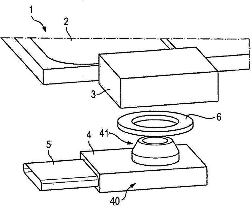
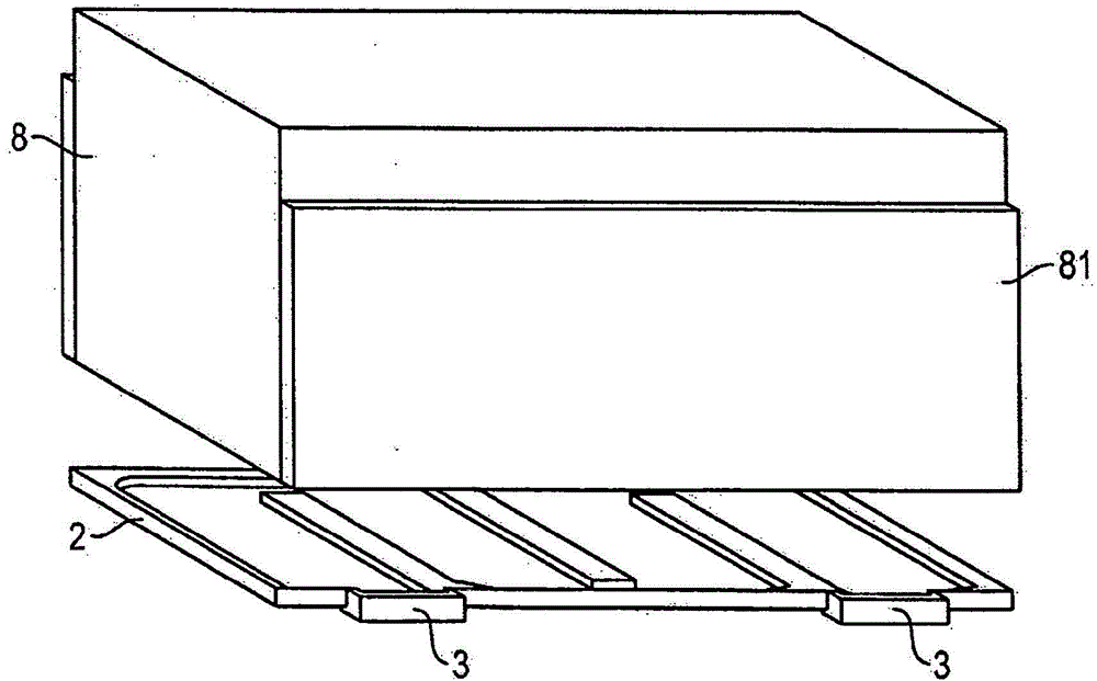
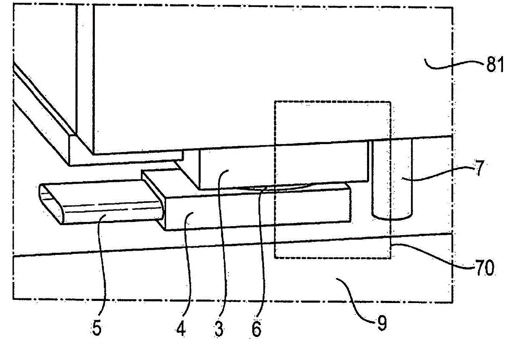
[0028] figure 1 A schematic diagram of a first embodiment of the cooling device 1 according to the invention is shown. The cooling device 1 has a cooling element 2 which can be formed, for example, as a plate. The cooling element 2 is used to receive and discharge the heat of the object 8 connected to the cooling element 2 (see figure 2 ). In addition, the cooling element 2 is connected to a first cooling connector 3, which forms an interface for leading out and / or introducing a cooling fluid. To this end, the first cooling connector 3 has an opening into which the pin 41 of the second cooling connector 4 can be embedded. The pin 41 is provided on the connecting part 40 of the second cooling connector 4 and can realize the transfer of the cooling fluid from the first cooling connector 3 to the second cooling connector 4. The cooling fluid can be, for example, a direct refrigerant or a water-glycol mixture. In order to prevent the cooling fluid from being discharged from the...


PUM


Abstract

The invention relates to a cooling device (1), particularly for a battery, comprising a cooling element (2) that can be connected to an object (8) to be cooled, a first cooling connector (3) connected to the cooling element (2), and a second cooling connector (4) that can be supported on an installation plate (9). The first cooling connector (3) and the second cooling connector (4) are designed to be connectable in such a manner that a transition of a cooling fluid from the first cooling connector (3) to the second cooling connector (4) is possible.

Description

Technical field [0001] The invention relates to a cooling device for an object to be cooled, especially for a battery module. Furthermore, the present invention relates to a vehicle in which such a cooling device is present and is preferably used for cooling battery modules. Background technique [0002] It is in electric vehicles or hybrid vehicles that battery cells that usually must be cooled are used. This can be done, for example, by air or by liquid media, such as direct refrigerants or water-glycol mixtures. In order to be able to easily assemble the battery unit and simply replace it in the case of maintenance, when cooling with a liquid medium, in particular a refrigerant, the cooler is usually only mechanically tensioned and in contact with the battery unit. However, when the cooler is connected to the battery unit purely mechanically, the achievable cooling power is based on the additional thermal resistance of the interstitial medium between the cooler and the batte...

Claims


Application Information

Patent Timeline
Patent Type & Authority Applications(China)
IPC IPC(8): F28F3/12F28F9/02F28F9/26H01M10/613H01M10/6556H01M10/6568B60L11/18H01M50/204
CPCF28F2275/20H01M10/647F28F3/12B60L11/1879Y02T10/705F28F9/0246H01M10/613H01M10/6568F28F2275/14H01M2/1083B60L11/1874H01M10/6556Y02T10/7005H01M10/625F28F9/26B60L58/26B60L50/64Y02T10/70Y02E60/10H01M50/204F28D15/00F28F2275/00
Inventor F·布尔卡特T·霍夫勒T·伊迪科特F·兰德雷尔S·西林
Owner BAYERISCHE MOTOREN WERKE AG
Learn More