Dust collector tension pulley frame dislocation balancing structure

A technology of balanced structure and tensioner frame, applied in vacuum cleaners, cleaning equipment, household appliances, etc., can solve the problems of tensioner frame deviation, tensioner deviation, and inability to observe the vacuum cleaner in real time, and achieve the goal of overcoming tensioner deviation Effect

Active Publication Date: 2015-08-05
SUZHOU CHUNJU ELECTRIC CO LTD
View PDF6 Cites 1 Cited by
  • Summary
  • Abstract
  • Description
  • Claims
  • Application Information

AI Technical Summary

Problems solved by technology

The main disadvantage of the current structure is that when applying force to the tensioner frame, it is necessary to ensure that the force application point is as far as possible at the center point in the width direction of the tensioner frame, otherwise it is easy to cause the tensioner frame to shift to both sides , so that the front tight wheel will also be offset, and the braking effect will be affected or even invalid.
In the actual operation process, the user cannot observe the situation inside the vacuum cleaner in real time, and can only operate by pressing the external take-up button connected to the tensioner frame, so the probability of deviation is very high, which brings many problems to the user. inconvenience

Method used


Image

  • Dust collector tension pulley frame dislocation balancing structure
  • Dust collector tension pulley frame dislocation balancing structure
  • Dust collector tension pulley frame dislocation balancing structure

Examples


Embodiment Construction

[0037] Preferred embodiments of the present invention will be described in detail below in conjunction with the accompanying drawings.

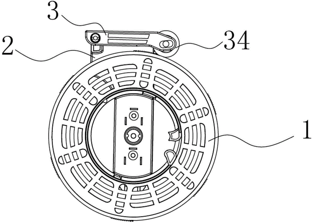
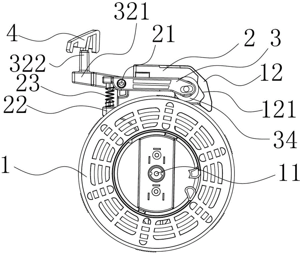
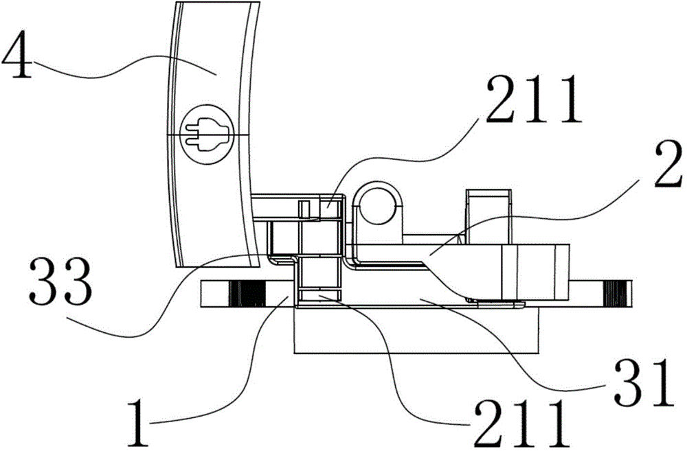
[0038] In order to achieve the purpose of the present invention, as Figure 2-7 As shown, in some embodiments of the dislocation balance structure of the vacuum cleaner tensioner frame of the present invention, it is installed at the reel 1, which includes a tensioner frame bracket 2 and a tensioner frame frame 3, and the tension wheel frame bracket 2 is rotatably connected to The rotating shaft 11 of the reel 1 is provided with a shaft body 21 transversely on the tensioner bracket bracket 2, and the first connecting portion 211 is formed at both ends thereof; the tensioner frame 3 includes a first frame unit 31 and a second Frame body unit 32, the side parts of the first frame body unit 31 and the second frame body unit 32 are fixedly connected or integrally formed to form overlapping joints 33, and the two outer sides of the joints 33 are p...


PUM


Abstract

The invention discloses a dust collector tension pulley frame dislocation balancing structure, which is arranged on a winding roll, and comprises a tension pulley frame support and a tension pulley frame, wherein the tension pulley frame support is rotatably connected on a rotating shaft of the winding roll, a shaft body is arranged on the tension pulley frame support in the transverse direction, first connecting portions are formed on the two end portions of the tension pulley frame support, the tension pulley frame comprises a first frame unit and a second frame unit which are arranged in a dislocation mode, second connecting portions which are corresponding to the first connecting portions are arranged on the two outer sides of a connecting position of the first and the second frame units, the tension pulley frame is rotatably connected on the tension pulley frame support through the first and the second connecting portions, a free end of the first frame unit is rotatably connected with a tension pulley, and a free end of the second frame unit is used as a point of application. Compared with the prior art, the dust collector tension pulley frame dislocation balancing structure does not need to guarantee the point of application on a center position of the tension pulley frame, and just needs to apply force on the free end of the second frame unit, thereby being capable of effectively overcoming a shift phenomenon of the tension pulley because the point of application shifts a center in the prior art.

Description

technical field [0001] The invention relates to a vacuum cleaner tension wheel frame, in particular to a vacuum cleaner tension wheel frame dislocation balance structure. Background technique [0002] In vacuum cleaners, especially horizontal vacuum cleaners, the tensioner frame is a common component, and its main function is to brake the wire reel, so that the wire reel can no longer rotate by itself to take up the wire. [0003] The current tensioner frame structure such as figure 1 As shown, it mainly includes the tension wheel frame 3, the tension wheel 34 and the tension wheel frame bracket 2, the tension wheel frame 3 is in the shape of a rod body, and it is installed on the tension wheel frame bracket 2, and the tension wheel 34 in front of the tension wheel frame 3 Then it is used to form a braking effect on the winding reel 1 . The main disadvantage of the current structure is that when applying force to the tensioner frame, it is necessary to ensure that the forc...

Claims


Application Information

Patent Timeline
Patent Type & Authority Applications(China)
IPC IPC(8): A47L9/00
Inventor 焦卫东
Owner SUZHOU CHUNJU ELECTRIC CO LTD
Why Eureka
Try Eureka