Emergency braking device for elevator

A technology of emergency braking and elevators, applied in transportation, packaging, elevators, etc., can solve problems such as elevator safety accidents, and achieve the effect of simple structure

Inactive Publication Date: 2015-02-11
STATE GRID CORP OF CHINA +1
View PDF7 Cites 12 Cited by
  • Summary
  • Abstract
  • Description
  • Claims
  • Application Information

AI Technical Summary

Problems solved by technology

[0003] In order to solve the problem of safety accidents caused by the elevator falling in the existing emergency situation, the present invention provides an elevator emergency braking device

Method used


Image

  • Emergency braking device for elevator
  • Emergency braking device for elevator
  • Emergency braking device for elevator

Examples


Embodiment Construction

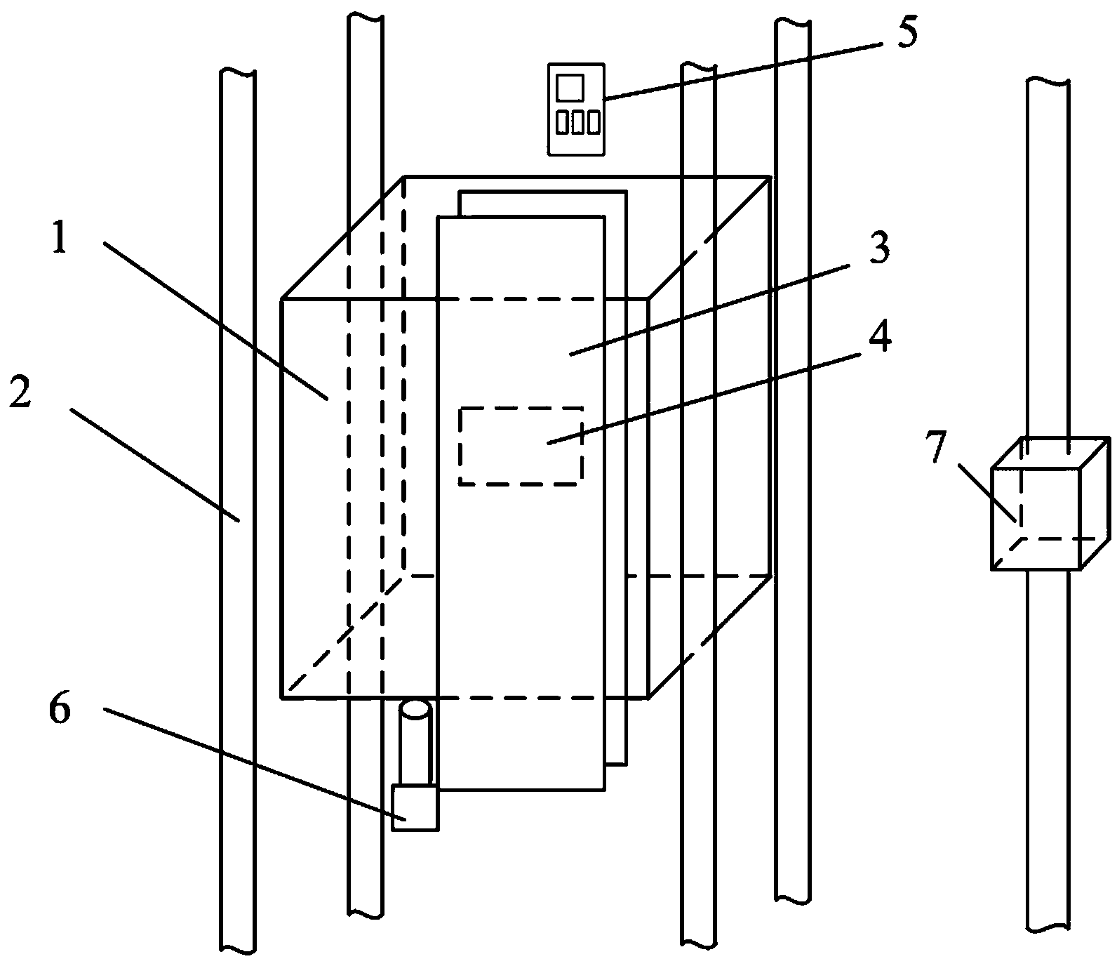
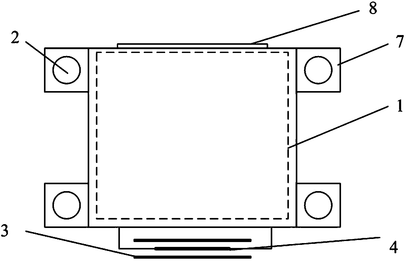
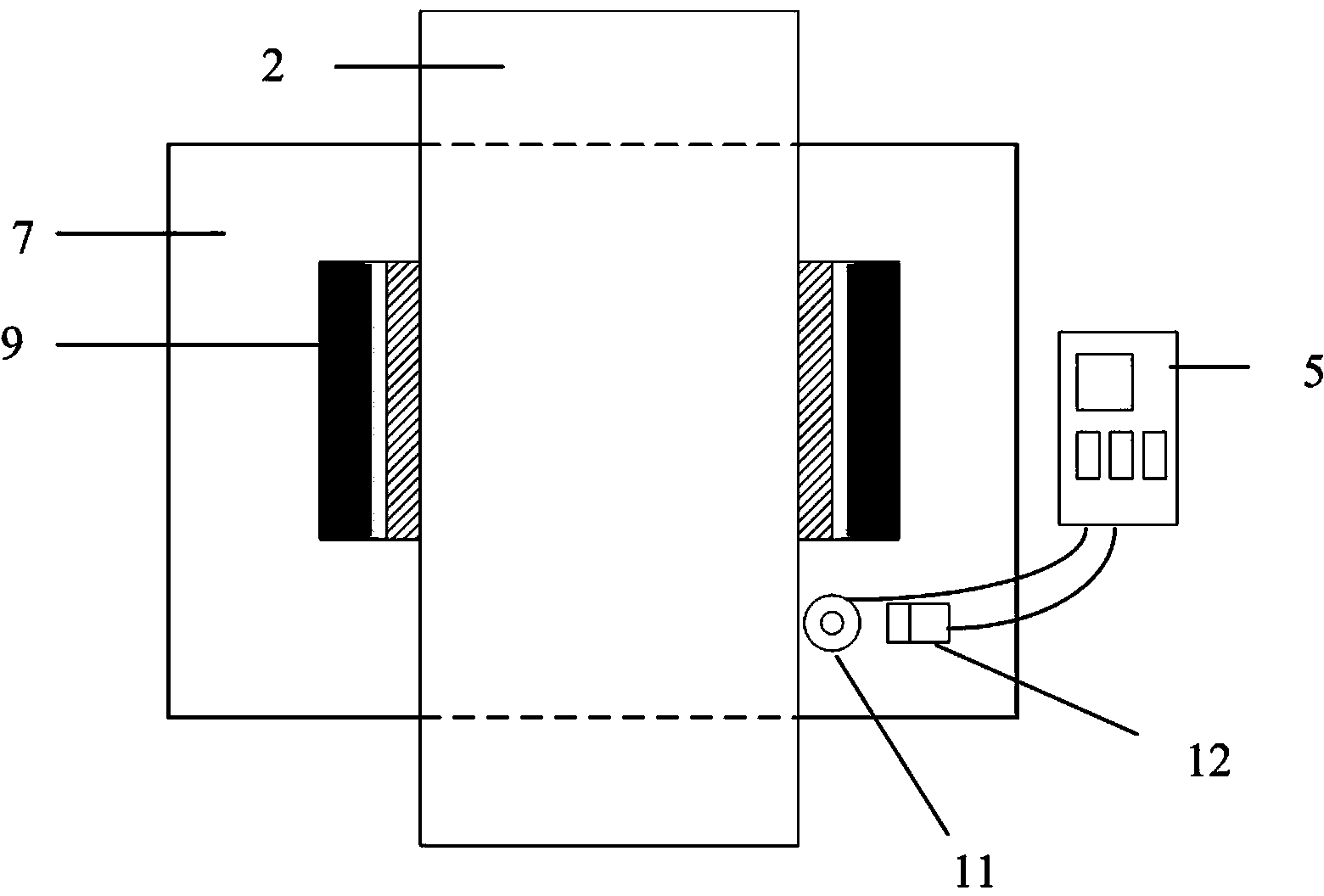
[0015] The elevator emergency braking device includes brake blocks 7 fixed at the four corners of the car 1, inside the brake blocks 7 there are cylindrical guide rails 2, and the cylindrical guide rails 2 lead from the bottom of the hoistway to the top. Including the brake friction plate 9, the piston 10 is connected behind the brake friction plate 9, the speed sensor 11 and the acceleration sensor 12 are also arranged in the brake block 7, and two rows of fixing plates 3 are arranged on the outside of the back of the car 1 (car 1 One side of the elevator door 8 is the front, and the opposite side is the back), the fixed plate 3 leads from the bottom of the hoistway to the top, and the conductive plate 4 fixed on the back of the car 1 is arranged between the two rows of fixed plates 3. Several groups of permanent magnets 13 with opposite polarities are arranged on the inside of the two rows of fixed plates 3, induction coils are arranged inside the conductive plate 4, a main c...


PUM


Abstract

The invention particularly relates to an emergency braking device for an elevator, and solves the existing problem of safety accidents caused by falling of the elevator under emergency circumstances. The emergency braking device for the elevator comprises braking blocks which are arranged on cylindrical guide rails in a penetrating manner, wherein braking friction plates are arranged in each braking block, the back parts of the braking friction plates are connected with pistons, and a speed sensor and an acceleration sensor are also arranged in each braking block; two rows of fixing plates are arranged on the outer side of the back of an elevator car, a conductive plate is arranged between the two rows of the fixing plates, multiple groups of permanent magnets with opposite polarities are arranged on the inner sides of the two rows of the fixing plates, and an induction coil is arranged in the conductive plate; a main controller is arranged at the top of the elevator car; a hydraulic pump is arranged at the bottom of the elevator car, and the hydraulic pump is connected to the pistons through a hydraulic pipeline; the main controller is connected to all the conductive plate, the hydraulic pump, the speed sensor and the acceleration sensor, and the conductive plate is also connected with the hydraulic pump. The emergency braking device disclosed by the invention has the advantages of simple structure, high safety and effectiveness, and on the premise that the normal operation of the elevator is not influenced, the situation that the elevator is braked under the emergency circumstances such as power failure and the like can be realized.

Description

technical field [0001] The invention relates to elevator equipment, in particular to an elevator emergency braking device. Background technique [0002] The elevator brakes used at present are all placed in the machine room at the top of the hoistway, and are used to ensure that the elevator car stops safely when the car stops at the lifting platform. When in an emergency situation, such as the friction coefficient of the brake pads decreases, the cable breaks, etc., the car loses its traction and falls rapidly, posing a threat to the life safety of the elevator personnel. Contents of the invention [0003] The present invention provides an elevator emergency braking device in order to solve the problem of safety accidents caused by the elevator falling in the existing emergency situation. [0004] The present invention is realized by adopting the following technical scheme: the elevator emergency braking device includes brake blocks fixed at the four corners of the car, ...

Claims


Application Information

Patent Timeline
Patent Type & Authority Applications(China)
IPC IPC(8): B66B5/18
CPCB66B5/18
Inventor 石慧张平李世英
Owner STATE GRID CORP OF CHINA
Why Eureka
Try Eureka