Brake cylinder of hydraulic brake device of railway vehicle

A technology for hydraulic braking and rail vehicles, applied in the direction of brake types, brake actuators, slack adjusters, etc., can solve the problems of many moving parts, hidden safety hazards, difficult processing and assembly, etc., and achieve less moving parts and high reliability Tall, compact effect

Active Publication Date: 2014-01-01
DALIAN HUARUI HEAVY IND GRP CO LTD
View PDF9 Cites 8 Cited by
  • Summary
  • Abstract
  • Description
  • Claims
  • Application Information

AI Technical Summary

Problems solved by technology

The brake caliper belongs to the active type, that is, the hydraulic oil is pressed to brake, and the hydraulic oil is released to release the brake. It has the following shortcomings: First, the brake caliper does not have the function of automatic gap compensation, so as As the number of times increases, the gap between the surface of the friction plate and the surface of the brake disc will continue to increase, resulting in prolonged braking time; second, the brake caliper does not have a detection device for the wear of the friction plate and brake disc, and can only be manually It is not easy to find the problem in time, and there are certain safety hazards; third, the brake caliper cannot provide pressure oil when the hydraulic system fails or the circuit fails, so it cannot achieve braking.
The structure of the brake cylinder with this structure is complicated, the processing and assembly of parts are difficult, there are many moving parts, the possibility of failure is high, the

Method used


Image

  • Brake cylinder of hydraulic brake device of railway vehicle
  • Brake cylinder of hydraulic brake device of railway vehicle
  • Brake cylinder of hydraulic brake device of railway vehicle

Examples


Embodiment Construction

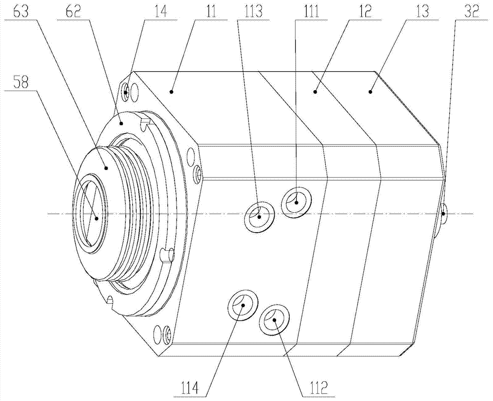
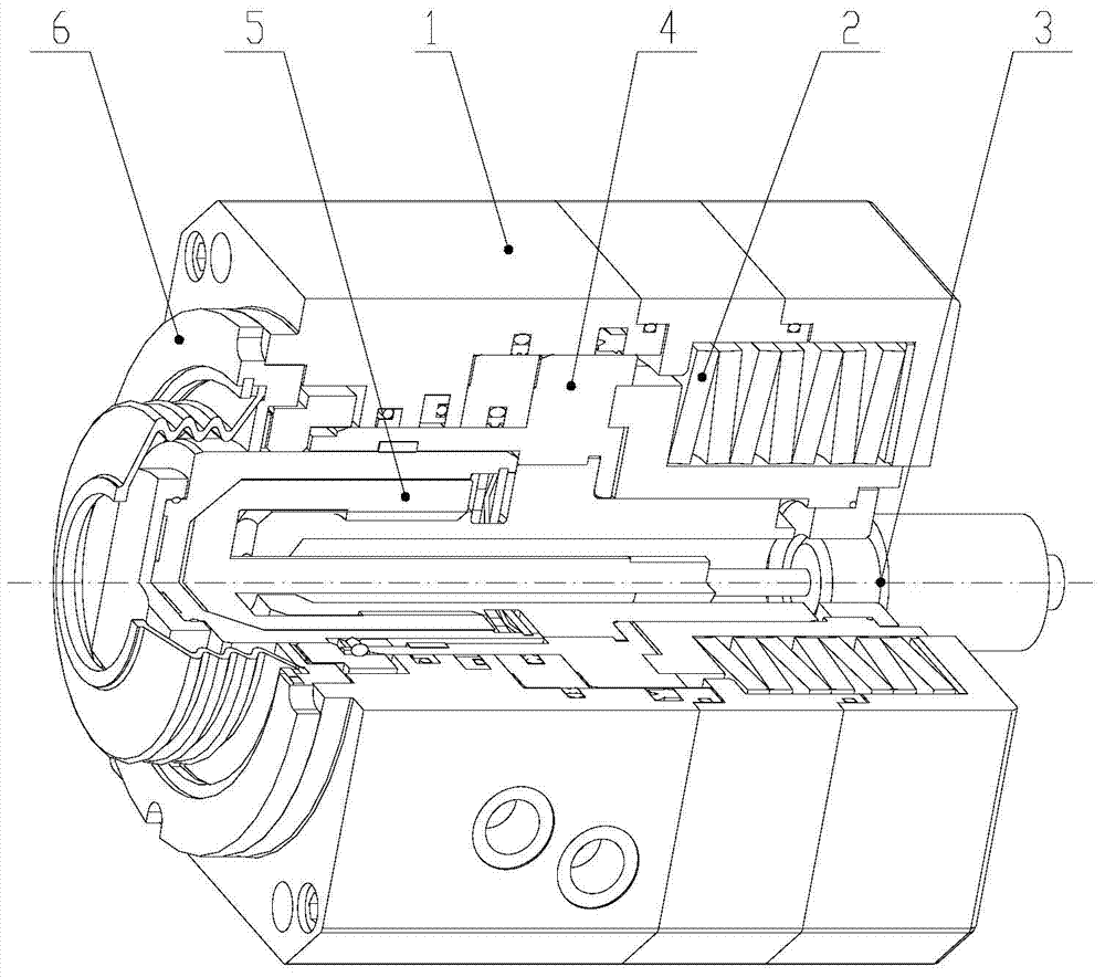
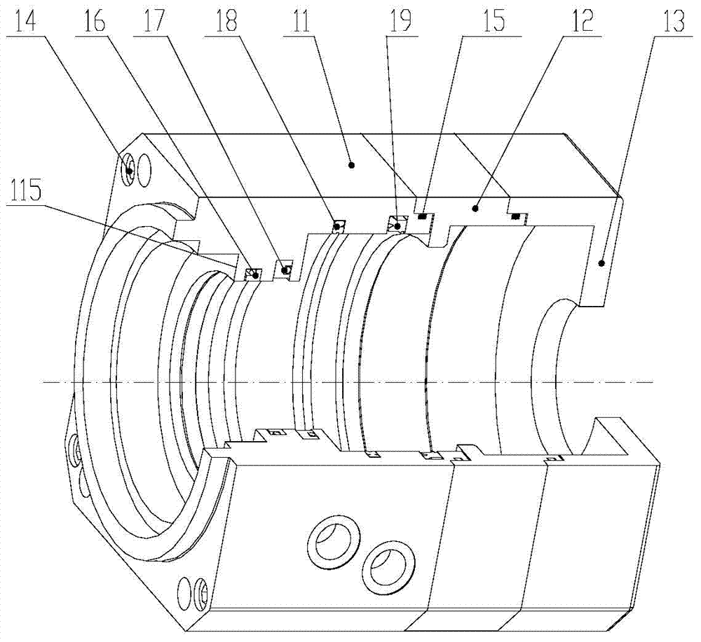
[0050] The present invention will be further described below in conjunction with the accompanying drawings. Such as Figure 1-15 As shown, a brake cylinder of a rail vehicle hydraulic brake device includes a housing member 1, a disc spring assembly 2, an indicator assembly 3, a piston assembly 4, a push rod assembly 5 and an end cover assembly 6, the push rod assembly 6 The rod assembly 5, the piston assembly 4, the disc spring assembly 2, and the indicator assembly 3 are sequentially installed in the cylindrical hole with steps inside the housing member 1 from front to rear and are the same as the main axis of the housing member 1, and the end cover assembly 6 Installed on the cylindrical step of the front end of the housing member 1 and the axis is the same as the main axis of the housing member 1;

[0051] The housing member 1 is cylindrical in shape with an outer side and an inner circle, and is connected from front to back by four screws 14 whose length is less than the ...


PUM


Abstract

The invention discloses a brake cylinder of a hydraulic brake device of a railway vehicle. The brake cylinder comprises a shell component, a disk spring assembly, an indicator assembly, a piston assembly, a push rod assembly and an end cover assembly. The push rod assembly, the piston assembly, the disk spring assembly and the indicator assembly are sequentially installed in a cylindrical hole inside the shell component from front to back, wherein the cylindrical hole is provided with a step, and the axis of the push rod assembly, the axis of the piston assembly, the axis of the disk spring assembly, and the axis of the indicator assembly are the same as the main axis of the shell component. The end cover assembly is installed on the cylindrical step at the front end of the shell component, and the axis of the end cover assembly is the same as the main axis of the shell component. Brake clearances can be automatically compensated by multiple threads. Compared with an existing brake cylinder, the brake cylinder is simple in structure, convenient to machine and assemble, few in movable parts, and high in reliability, has the friction plate and brake disc abrasion monitoring function and the automatic compensation mechanism running real-time monitoring function, and can remotely monitor the working state of the brake cylinder in real time. Manual brake loosening and adjustment can be achieved on the scene through a manual mechanical brake loosening device, and operation is conveniently and quickly conducted.

Description

technical field [0001] The invention relates to the field of rail vehicle braking, in particular to a brake cylinder of a rail vehicle hydraulic braking device. Background technique [0002] The braking system is an important safety device for rail vehicles, which is related to the life and property safety of passengers and pedestrians. Traditional rail vehicle braking devices generally use air brakes, and the structural layout makes the structure of the brake cylinder huge and complicated, which cannot be installed on rail vehicles with a small space under the car body. The hydraulic braking system is small in size and can be installed on the bogie nearby. [0003] The main component of the hydraulic braking system is the brake cylinder of the hydraulic braking device. During the use of the braking system of rail transit vehicles, it is easy to cause wear of the friction lining and the brake disc, thereby increasing the gap between the friction lining and the brake disc. ...

Claims


Application Information

Patent Timeline
IPC IPC(8): F16D66/02F16D65/52F16D65/14F16D121/04F16D125/02
Inventor 董连俊宋玉涛杨京兰陈强史显忠
Owner DALIAN HUARUI HEAVY IND GRP CO LTD
Why Eureka
Try Eureka