Hydraulic hose rinser

The technology of a flusher and a rubber hose is applied in the field of hydraulic machinery in coal mines, which can solve problems such as hidden safety hazards, achieve the effects of convenient installation, avoid manual operation with pressure, and eliminate safety threats

Inactive Publication Date: 2015-08-05
HUAINAN MINING IND GRP
View PDF7 Cites 1 Cited by
  • Summary
  • Abstract
  • Description
  • Claims
  • Application Information

AI Technical Summary

Problems solved by technology

However, due to the pressure flushing used in the flushing process, there are potential safety hazards caused by manual pressure operation

Method used


Image

  • Hydraulic hose rinser
  • Hydraulic hose rinser
  • Hydraulic hose rinser

Examples


Embodiment Construction

[0029] In order to make the purpose, technical solutions and advantages of the embodiments of the present invention clearer, the technical solutions in the embodiments of the present invention will be clearly and completely described below in conjunction with the drawings in the embodiments of the present invention. Obviously, the described embodiments It is a part of embodiments of the present invention, but not all embodiments. Based on the embodiments of the present invention, all other embodiments obtained by persons of ordinary skill in the art without creative efforts fall within the protection scope of the present invention.

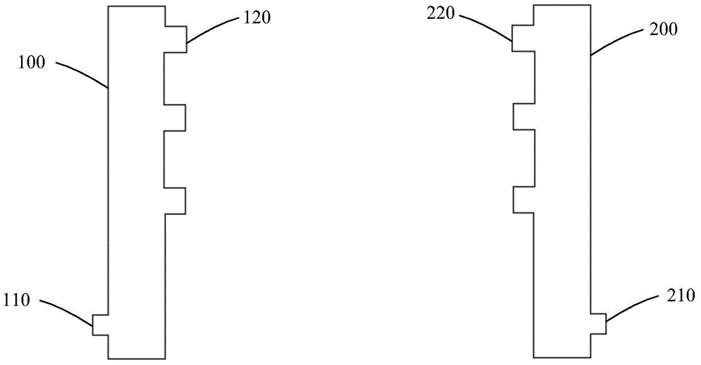
[0030] figure 1 The schematic structural diagram of the hydraulic rubber hose flusher provided in Embodiment 1 of the present invention, as shown in figure 1 As shown, the hydraulic hose flusher provided in this embodiment may include: a water inlet 100 and a drain 200 that are separated from each other.

[0031] The water inlet 100 is closed an...


PUM


Abstract

The invention discloses a hydraulic hose rinser which comprises a water feeder and a drainer being separated to each other, wherein the water feeder is sealed and hollow and is provided with a water inlet; at least one two-way device is arranged on the side wall of the water feeder; the drainer is sealed and hollow and is provided with a water outlet; a two-way device matched with the two-way device on the side wall of the water feeder is arranged on the side wall of the drainer. The hydraulic hose rinser eliminates security risk caused by artificial pressure operation and improves the washing efficiency of the hydraulic hose.

Description

technical field [0001] The invention relates to the field of coal mine hydraulic machinery, in particular to a hydraulic hose flusher. Background technique [0002] In the comprehensive mechanized mining process of coal mines, hydraulic support is an indispensable supporting equipment. The hydraulic support is a hydraulic power device used to control the mine pressure of the coal mining face. It uses the liquid pressure to generate support force and realize automatic transfer for roof support and management. [0003] In hydraulic supports, hydraulic hoses are used to transport petroleum-based (such as mineral oil, soluble oil, hydraulic oil, fuel oil, lubricating oil) and water-based liquids (such as emulsion, oil-water emulsion, water) with a certain pressure and temperature. , through the transmission of liquid to achieve high-pressure fluid delivery and hydraulic power transmission. Whether the inside of the hydraulic hose is clean or not greatly affects the safety of t...

Claims


Application Information

Patent Timeline
Patent Type & Authority Applications(China)
IPC IPC(8): B08B9/032
CPCB08B9/0321B08B2209/032
Inventor 王冲何文献秦克军闻庆祝郝井涛
Owner HUAINAN MINING IND GRP
Why Eureka
Try Eureka