
A glass cutting machine tool holder mechanism

A cutting machine and knife holder technology, applied in the direction of glass cutting devices, glass manufacturing equipment, manufacturing tools, etc., can solve the problems of weak strength and low glass cutting efficiency, and achieve the effect of efficient oil change

Active Publication Date: 2018-07-31
ANHUI SCI & TECH UNIV
View PDF3 Cites 0 Cited by
  • Summary
  • Abstract
  • Description
  • Claims
  • Application Information

AI Technical Summary

Problems solved by technology

[0005] The technical problems to be solved by the present invention are: 1. In the existing cutting machine, manual tool changer is used, which results in low cutting efficiency of various glass with different functions; Oil is inconvenient; 3. The existing glass cutting machine needs to manually adjust the cutting pressure generated by the cutter on the glass according to experience. The cutting pressure cannot be visualized and digitized. If the type changes, the cutting pressure needs to be readjusted, which is labor-intensive and time-consuming, requiring high technical level of workers, and the tool holder is not very adaptable to the small fluctuations of the glass

Method used


Image

  • A glass cutting machine tool holder mechanism
  • A glass cutting machine tool holder mechanism
  • A glass cutting machine tool holder mechanism

Examples


Embodiment 1

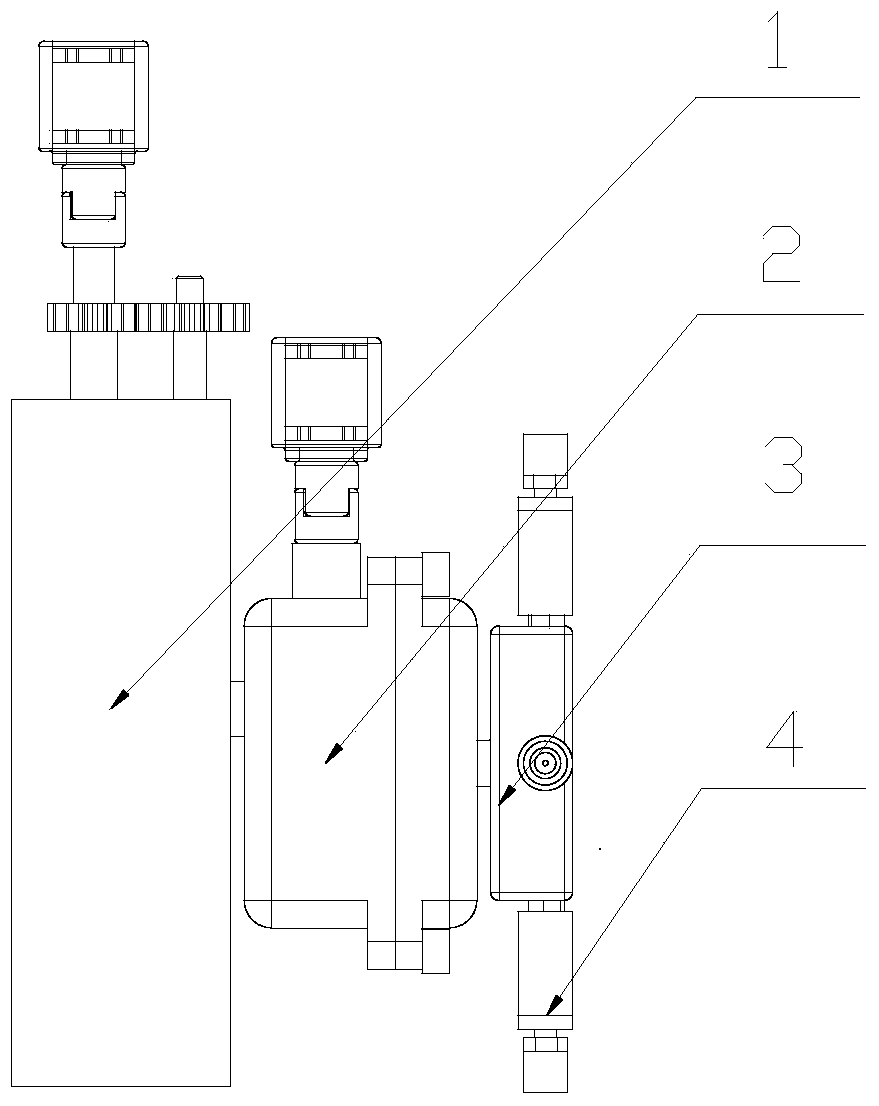
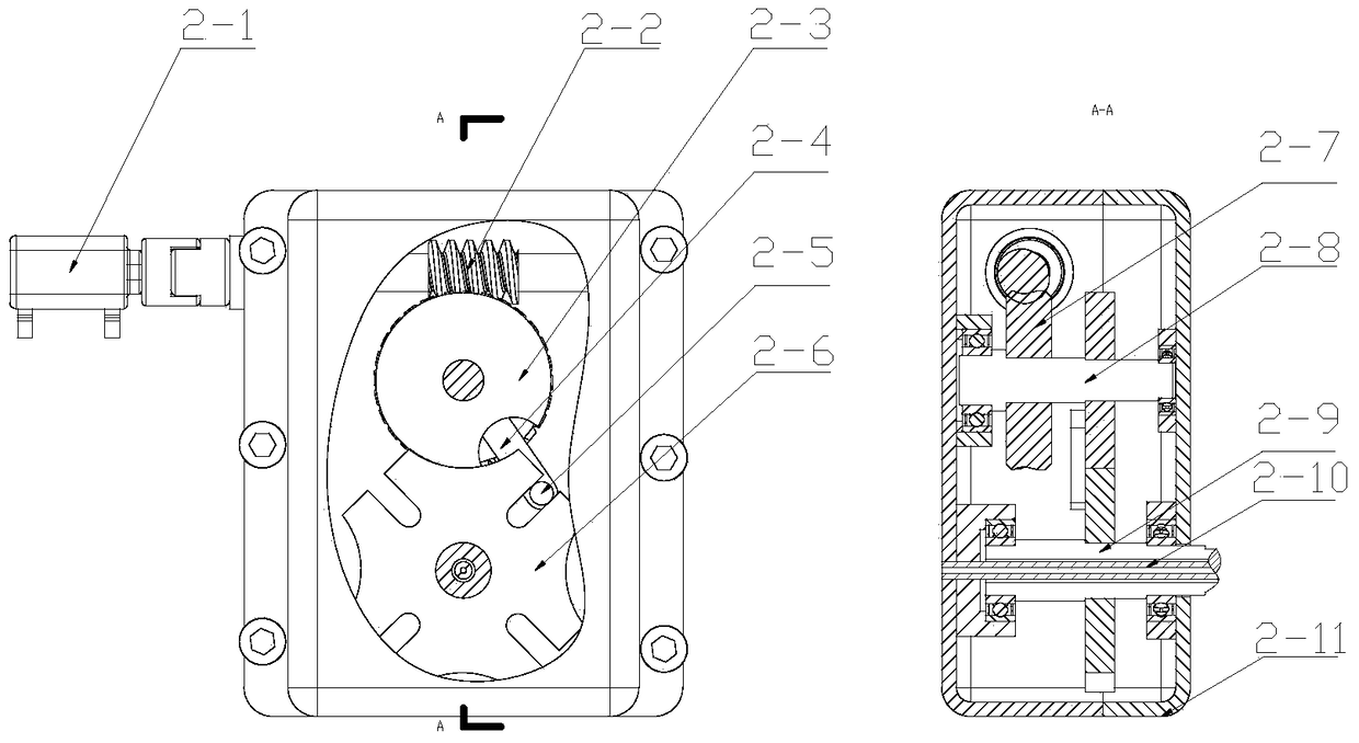
[0021] Embodiment 1 A knife holder mechanism for a glass cutting machine, including a rotatable knife holder 3, a fixed knife seat 2 for driving the rotatable knife holder 3 to rotate, and a tool clamping device 4, along the outer surface of the rotatable knife holder 3. Its rotation direction is provided with more than two tool clamping devices 4, and the fixed tool seat 2 includes a first servo motor 2-1, a worm screw 2-2, a worm wheel 2-7, a transmission shaft 2-8, and a notch disc 2 -3. The rotating arm 2-4, the sheave 2-6 and the rotary hollow main shaft 2-9, the first servo motor 2-1 is connected with the worm 2-2, and the worm 2-2 is in phase with the worm wheel 2-7 meshing, the worm wheel 2-7 and the notch disc 2-3 are fixed on the transmission shaft 2-8, the notch disc 2-3 is engaged with the sheave 2-6 and drives the sheave 2-6 to rotate, Preferably, the notched disc 2-3 is connected to the cylindrical pin 2-5 through the rotating arm 2-4, and the slots of the sheave...

Embodiment 2

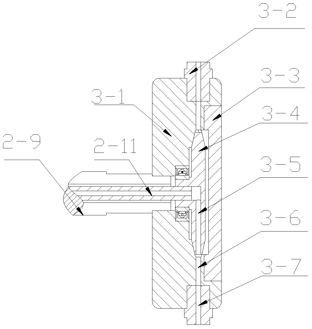
[0022] Embodiment 2 On the basis of Embodiment 1, preferably, the rotatable tool holder 3 includes a tool holder shell 3-1, a stud 3-2, a knife holder sealing cover 3-3 and a fixed oil storage pan 3 -4, the tool rest shell 3-1 is cylindrical, and along the central axis of the tool rest shell 3-1, a stepped hole and a first semi-closed cavity are sequentially arranged on the tool rest shell 3-1 Body, on the inner wall of the first semi-closed cavity body, a first oil passage 3-6 is provided along the radial direction of the tool holder shell 3-1, and a first oil passage 3-6 is provided on the tool holder sealing cover 3-3. Two semi-closed hollow bodies, the knife rest sealing cover 3-3 is detachably connected on the knife rest shell 3-1, after the knife rest sealing cover 3-3 is connected with the knife rest shell 3-1, the first The semi-closed cavity body and the second semi-closed cavity body form a closed cavity body, and the shape of the closed cavity body matches the shape...

Embodiment 3

[0023] Embodiment 3 On the basis of Embodiment 2, the fixed tool holder 2 further includes a fixed hollow shaft 2-10, and the fixed hollow shaft 2-10 runs through the center axis of the rotary hollow main shaft 2-9. In the rotary hollow main shaft 2-9, one end of the fixed hollow shaft 2-10 is fixedly mounted on the tool seat shell 2-11, and the other end is interference fit with the axial blind hole of the fixed oil storage tray 3-4, The fixed hollow shaft is used as an oil channel for oil delivery.


PUM


Abstract

The invention discloses a knife holder mechanism for a glass cutting machine, comprising a rotatable knife holder (3), a fixed knife seat (2) for driving the rotatable knife holder (3) to rotate, and a tool clamping device (4). The outer surface of the rotatable tool holder (3) is provided with more than two tool clamping devices (4) along its direction of rotation. The rotating hollow spindle of the fixed tool holder drives the rotatable tool holder to rotate, and the rotatable tool holder passes through the tool The clamping device is connected with multiple tools, and the purpose of automatic tool change is realized by rotating the rotatable tool holder. At the same time, the fixed hollow shaft in the tool holder, the second oil passage of the fixed oil storage plate, and the first oil passage of the tool holder shell are fixed. , the third oil channel of the double-ended stud and the channel of the taper sleeve connecting the shaft constitute a complete oil change oil circuit, which can realize high-efficiency oil change.

Description

technical field [0001] The invention relates to a glass cutting machine knife rest mechanism, in particular to a flexible and multifunctional integrated glass cutting machine knife rest mechanism. technical background [0002] At present, the technology of glass cutting machines at home and abroad is becoming more and more mature. On the existing glass cutting machine, only one knife holder can be installed on one knife holder, and one knife holder can only hold one knife. Tool change is labor-intensive and inefficient. Modern glass cutting requires multiple processes such as film removal, lubrication, cutting, and sanding. Multiple tools are required, and tool change is cumbersome. Even multiple sets of equipment are required to complete the above processes, which cannot meet the requirements of LOW- E glass, frosted glass and ordinary glass and other glass cutting needs of different functions. [0003] In addition, when cutting glass, it is necessary to inject the glass c...

Claims


Application Information

Patent Timeline
Patent Type & Authority Patents(China)
IPC IPC(8): C03B33/00
Inventor 陈丰张海涛宛传平徐幸项军
Owner ANHUI SCI & TECH UNIV
Learn More