Suction shield head for seabed sand suction operation

A shield head and water inlet technology, applied in mechanically driven excavators/dredgers, etc., can solve the problems of material wear, large resistance, and high requirements for equipment materials, and achieve high efficiency, reasonable structure design, and high sand suction efficiency. Effect

Inactive Publication Date: 2015-08-05
MINGGUANG CITY LIUXIANG PUMP IND
View PDF7 Cites 0 Cited by
  • Summary
  • Abstract
  • Description
  • Claims
  • Application Information

AI Technical Summary

Problems solved by technology

[0002] Most of the existing domestic seabed sand mining equipment is a hydraulic machine in which the motor and the water pump are coaxially submerged into the medium, or the sand is directly excavated by the sand suction pump, which has high requirements on the material of the equipment, large resistance during operation, and serious material wear.

Method used


Image

  • Suction shield head for seabed sand suction operation
  • Suction shield head for seabed sand suction operation
  • Suction shield head for seabed sand suction operation

Examples


Embodiment Construction

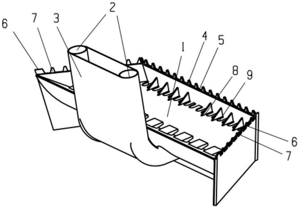
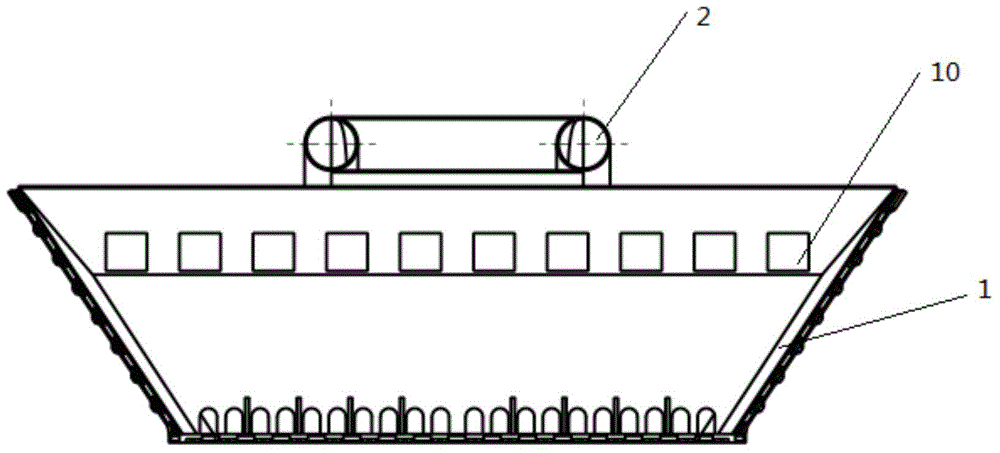
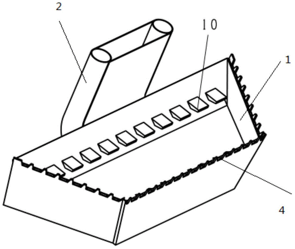
[0015] Referring to the accompanying drawings, the special suction shield for seabed sand suction operation includes a sand bin 1, the sand bin has a trapezoidal structure, and a water inlet 2 is welded on the front end of the sand bin, and the water inlet 2 is formed by two round pipes. Composition, the square structure in the middle of the water inlet 2 is the sand pumping port 3; there is a toothed structure 4 on the rear end surface of the sand bin 1, and the gap opened between the toothed structures 4 is the water outlet 5, and the sand bin 1 There are zigzag structures 6 respectively on the left and right end surfaces of the zigzag structures 6, and the gaps opened between the zigzag structures 6 are water outlets 7; the bottom surface of the sand bin 1 near the rear end surface is separated by a triangular plate 8 as a sand suction port. 9. A water outlet 10 is welded below the front end of the sand bin 1 .

[0016] When the special suction shield head for seabed sand s...


PUM


Abstract

The invention discloses a suction shield head for the seabed sand suction operation. The suction shield head comprises a sand bin. The upper end is in a trapezoid shape. A water inlet is welded at the front end of the sand bin and formed by two round tubes, and the square structure in the middle of the water inlet is formed into a sand pumping port. A tooth-shaped structure is arranged on the upper portion of the rear end of the sand bin, and water outlets are formed in gaps among the tooth-shaped structure, zigzag structures are arranged at the left and right ends of the sand bin, and gaps formed among the zigzag structures are water outlets. Grooves isolated by triangular plates are formed in the upper end of the sand bin close to the rear end to be formed into sand suction ports, and water outlets are welded on the portion at the upper end of the sand bin close to the front end. When the suction shield head operates, the tooth-shaped and zigzag structures are in contact with the operation faces, the round-tube structures are pulled by a ship to advance, high-pressure water flows in through the water inlet and sprayed through the water outlets, sand is raised by the sprayed high-pressure water, the raised sand is suctioned from sand suction ports, and water and sand mixtures are pumped out through the sand pumping port.

Description

technical field [0001] The invention relates to a seabed sand suction device, in particular to a special suction shield for seabed sand suction operations. Background technique [0002] Most of the existing domestic seabed sand mining equipment is a hydraulic machine in which the motor and the water pump are coaxially submerged into the medium, or the sand is directly excavated by the sand suction pump, which has high requirements on the material of the equipment, high resistance during operation, and serious material wear. Contents of the invention [0003] The purpose of the present invention is to make up for the deficiencies of the prior art, and to provide a special suction shield for seabed sand suction operations. [0004] When the special suction shield for seabed sand suction operation is working, the tooth-shaped and zigzag structures contact the working surface, and the suction shield is dragged forward by the boat, and the high-pressure water enters from ...

Claims


Application Information

Patent Timeline
Patent Type & Authority Applications(China)
IPC IPC(8): E02F3/92
Inventor 刘和明刘和兵
Owner MINGGUANG CITY LIUXIANG PUMP IND
Why Eureka
Try Eureka