Prediction method of thermal fatigue life of BGA (Ball Grid Array) welding spot considering influence of sequential temperature cycling load loading

A load sequence and life prediction technology, applied in special data processing applications, instruments, electrical digital data processing, etc., can solve the problems of no mature methods and limited research work, and achieve the effect of engineering application value

Active Publication Date: 2015-08-05
BEIHANG UNIV
View PDF12 Cites 20 Cited by
  • Summary
  • Abstract
  • Description
  • Claims
  • Application Information

AI Technical Summary

Problems solved by technology

However, for the most important thermal fatigue in solder joint fatigue, the existing life prediction model under the condition of temperature cycle cannot consider the influence of load sequence when the loading conditions change, and the application of Miner theory to linear accumulation results will have large errors, and the corresponding The research work is very limited, and there is no mature method for easy application

Method used


Image

  • Prediction method of thermal fatigue life of BGA (Ball Grid Array) welding spot considering influence of sequential temperature cycling load loading
  • Prediction method of thermal fatigue life of BGA (Ball Grid Array) welding spot considering influence of sequential temperature cycling load loading
  • Prediction method of thermal fatigue life of BGA (Ball Grid Array) welding spot considering influence of sequential temperature cycling load loading

Examples


Embodiment Construction

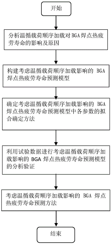
[0036] The BGA solder joint thermal fatigue life prediction method considering the impact of temperature cycle load sequence loading according to the present invention, see figure 1 As shown, the specific implementation steps of the method are as follows:

[0037] Step 1. According to the test data, the influence and reason of sequential loading of temperature cycle load on the thermal fatigue life of BGA solder joints are analyzed.

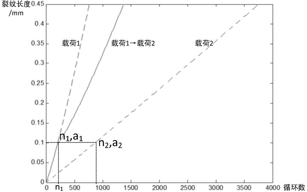
[0038] The influence of sequential loading of temperature cycle load on the thermal fatigue life of BGA solder joints is as follows: when the temperature cycle load is loaded sequentially from high to low, the fatigue life measured in the thermal fatigue test of BGA solder joints is shorter than the fatigue life predicted by Miner theory, while When the temperature cycle load is loaded sequentially from low to high, the fatigue life measured by the test is longer than that predicted by Miner's theory.

[0039] The reasons for the above effects a...


PUM


Abstract

The invention discloses a prediction method of a thermal fatigue life of a BGA (Ball Grid Array) welding spot considering an influence of sequential temperature cycling load loading. The method comprises the steps of 1, analyzing the influence of the sequential temperature cycling load loading on the thermal fatigue life of the BGA welding spot, and a reason; 2, improving a Darveaux model according to the influence of the sequential temperature cycling load loading on the thermal fatigue life of the BGA welding spot and by reference to a Paris formula and building a prediction model of the thermal fatigue life of the BGA welding spot considering the influence of the sequential temperature cycling load loading; 3, determining a fit determination method of parameters in the prediction model of the thermal fatigue life of the BGA welding spot considering the influence of the sequential temperature cycling load loading; 4, performing analysis verification on the prediction model of the thermal fatigue life of the BGA welding spot considering the influence of the sequential temperature cycling load loading, and separately performing contrast analysis on fatigue life prediction results of the prediction model of the thermal fatigue life of the BGA welding spot considering the influence of the sequential temperature cycling load loading and the Darveaux model under a single temperature cycling load condition, and performing contrast analysis on fatigue life prediction results of the prediction model of the thermal fatigue life of the BGA welding spot considering the influence of the sequential temperature cycling load loading and the Miner theory under a sequential temperature cycling load loading condition; and 5, completing building of the prediction method.

Description

technical field [0001] The invention relates to a method for predicting the thermal fatigue life of BGA solder joints considering the impact of sequential loading of different temperature cycle loads, and belongs to the technical field of failure physics. Background technique [0002] With the continuous development of electronic packaging technology, the field of application of electronic products is becoming more and more extensive, and the environmental conditions encountered in the use of electronic products are becoming more and more complex and harsh. There may be sudden changes in the environment, changes in working modes, etc., so that electronic products are loaded in sequence. under load conditions. BGA solder joints (ball grid array package solder joints) are a key link to ensure the reliability of electronic products, and the prediction and evaluation of their fatigue life is of great significance to products. However, for the most important thermal fatigue in s...

Claims


Application Information

Patent Timeline
Patent Type & Authority Applications(China)
IPC IPC(8): G06F19/00
Inventor 胡薇薇朱光远孙宇锋赵广燕陈浩
Owner BEIHANG UNIV
Why Eureka
Try Eureka