
Sample frame

A sample rack and carrier technology, applied in the field of sample racks, can solve the problems of increasing the risk of infection of experimental personnel, affecting the sampling of sampling needles, and limited space for fully automatic inspection equipment, etc.

Inactive Publication Date: 2015-08-12
ZHANGQIU YIHONGGUANG MEDICAL DEVICE
View PDF5 Cites 5 Cited by
  • Summary
  • Abstract
  • Description
  • Claims
  • Application Information

AI Technical Summary

Problems solved by technology

[0003] Fully automatic testing instruments need to pre-place the sample on a sample rack at a specific position, and most of the existing sample racks are only suitable for test tubes of the same specific specification, but there are many specifications for test tubes used in laboratories, and the sizes are different First, the existing single-size sample rack cannot place these test tubes. When the diameter of the test tube is smaller than the diameter of the sample rack hole, the test tube will be tilted when placed, so that the position of the sample will be skewed, and the sample needle cannot find an accurate position to draw the sample
Therefore, before the sample is tested, the experimenter must first transfer the sample to a test tube of a specific specification, which not only increases the workload of the experimenter, but also inevitably increases the probability of direct or indirect contact between the experimenter and the sample. Thereby increasing the risk of experimental personnel being infected
[0004] In addition, some foreign samples or samples that need to be stored and transported are generally stored in centrifuge tubes with sealed caps. When testing samples, the sealed caps of the centrifuge tubes need to be opened, while traditional sample racks do not have a structure to fix the sealed caps. After the cover is opened, it will cover the nozzle of itself or the surrounding centrifuge tubes, and it is easy to cross-contaminate between centrifuge tubes, and it will affect the sampling of the sampling needle
To avoid this situation, the interval between the centrifuge tubes must be increased, which takes up a lot of space, while the fully automatic inspection equipment has limited space and cannot provide enough space for the sealing cap

Method used


Image

  • Sample frame
  • Sample frame
  • Sample frame

Examples


Embodiment Construction

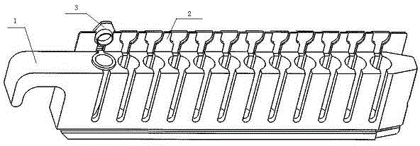
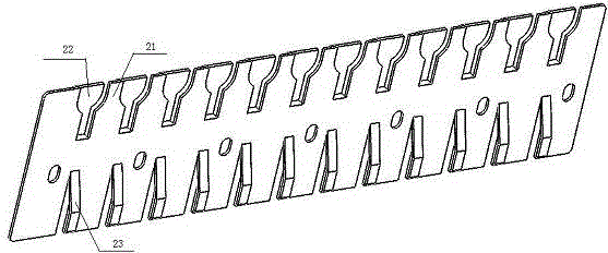
[0018] Such as Figure 1-Figure 4 As shown, the sample rack includes a carrier body 1 and a baffle plate 2, which are connected by screws and have a simple structure. The main body 1 of the carrier is provided with a round hole 11 for placing test tubes. Both sides of the round hole 11 are provided with strip-shaped slots 12. One end of the main body 1 of the carrier is provided with a handle 13 for easy access. The lower end of the baffle plate 2 is provided with a shrapnel 23, and the upper end baffle includes two parts, the front baffle 21 and the rear baffle 22. The front baffle 21 is provided with a semicircular hole consistent with the shape of the sealing cover of the centrifuge tube, and the rear baffle 22 is vertical to the rear. Stand upright after bending, the distance between the front blocking piece 21 and the rear blocking piece 22 is just the thickness of the edge of the sealing cover.

[0019] Specifically, the diameter of the round hole on the main body 1 of ...


PUM


Abstract

The invention provides a sample frame, which can adapt to test tubes and centrifuge tubes with different specifications, and aims at providing the sample frame which is simple in structure, high in practicability and suitable for full-automatic inspection equipment. The sample frame comprises two parts, namely a main carrier body and a baffle plate; the baffle plate is arranged on the side surface of the main carrier body; a plurality of round holes for arranging the test tubes are formed in the main carrier body; a spring sheet is arranged at the lower end of the baffle plate; and a seal cover fixing structure is arranged at the upper end of the baffle plate. The sample frame is simple in structure, relatively low in cost and high in practicability; the problem that an existing sample frame cannot hold the test tubes or centrifuge tubes with various specifications is solved; and the automatic degree of an instrument is improved.

Description

technical field [0001] The invention relates to the technical field of medical testing equipment, in particular to a sample rack capable of adapting to test tubes and centrifuge tubes of different specifications. Background technique [0002] With the advancement of science and technology, the degree of automation in the laboratory is getting higher and higher, and the requirements for automated instruments are also getting higher and higher. Fully automatic inspection equipment can not only liberate the labor force, improve work efficiency, but also avoid the possibility of personnel and samples. Direct contact with items that are harmful to health, thereby ensuring the safety of experimenters. Therefore, more and more automatic inspection instruments are used in the medical field. [0003] Fully automatic testing instruments need to pre-place the sample on a sample rack at a specific position, and most of the existing sample racks are only suitable for test tubes of the s...

Claims


Application Information

Patent Timeline
IPC IPC(8): B01L9/06
Inventor 郭宣城张利凡甘宜梧王绮谢清华
Owner ZHANGQIU YIHONGGUANG MEDICAL DEVICE
Learn More