Punching die for shield

A protective cover and punching technology, which is applied in the field of stamping die manufacturing, can solve the problems of low production efficiency and difficulty in clamping the limit holes of the protective cover, and achieve the effects of high production efficiency, easy clamping and firm installation.

Inactive Publication Date: 2015-08-12
GUANGXI WUZHOU YUNLONG PORT & SHIP MACHINERY MFG
View PDF7 Cites 3 Cited by
  • Summary
  • Abstract
  • Description
  • Claims
  • Application Information

AI Technical Summary

Problems solved by technology

[0003] The technical problem to be solved by the present invention is to provide a protective cover punching die to solve the problems of difficulty in mounting and clamping the mounting holes and limit holes of the protective cover and low production efficiency

Method used


Image

  • Punching die for shield
  • Punching die for shield

Examples


Embodiment Construction

[0013] The present invention will be described in further detail below in conjunction with accompanying drawing embodiment:

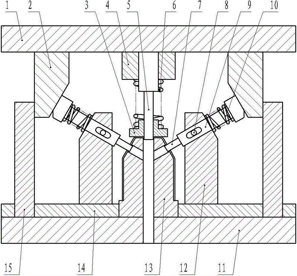
[0014] Such as figure 2 A shield punching die shown includes an upper mold base 1 and a lower mold base 11, and the lower end of the upper mold base 1 is equipped with an upper splint 4 and a first clamp that passes through the upper splint 4 and is affixed to the upper die base 1. Punch 5, the lower part of the first punch 5 is equipped with a discharge plate 3, and a discharge spring 6 is installed between the discharge plate 3 and the upper splint 4; the upper end of the lower mold base 11 is equipped with a workpiece positioning block 13 and Two support blocks 12 on both sides of the workpiece positioning block 13, each support block 12 is equipped with an oblique slide plate 9, the slide plate 9 is equipped with the second punch 7 stretching out to the workpiece positioning block 13, and the workpiece positioning block 13 Die holes corresponding ...


PUM


Abstract

The invention discloses a punching die for a shield, and relates to the technical field of punching die manufacturing. The punching die for the shield comprises an upper die base and a lower die base; the lower end of the upper die base is provided with a punch holder and a first punch; a discharging plate sleeves the lower part of the first punch; a discharging spring is arranged between the discharging plate and the punch holder; the upper end of the lower die base is provided with a workpiece locating block and two supporting shoes; a sliding plate penetrates through each supporting shoe; each sliding plate is provided with a second punch extending to the workpiece locating block; the upper part of each sliding plate is provided with a limiting boss; a reset spring is arranged between each limiting boss and the corresponding supporting shoe; the outer side of each supporting shoe is provided with a baffle; a stamping block of which the upper end is fixedly connected with the upper die base is arranged between each baffle and the corresponding supporting shoe; the outer side of each stamping block is abutted against the corresponding baffle; the inner side of each stamping block is provided with an oblique plane in compression joint with the corresponding limiting boss. Compared with the prior art, the punching die disclosed by the invention has the characteristics that the shield is arranged on the workpiece locating block, punching processing is performed on the shield by the first punch and the second punches simultaneously, the shield can be easily clamped, and the production efficiency is high.

Description

technical field [0001] The invention relates to the technical field of stamping die manufacturing, in particular to a punching die used for a protective cover. Background technique [0002] Such as figure 1 The protective cover shown has a cylinder and a cone connected to the upper end of the cylinder. The upper end of the cone is provided with a cover plate, and a mounting hole is provided on the cover plate. Two limit holes are provided on the wall of the cone cylinder. . Since there is no special punching die for the protective cover, it is difficult to process the installation hole and the limit hole of the protective cover, and the production efficiency is low. Contents of the invention [0003] The technical problem to be solved by the present invention is to provide a protective cover punching die to solve the problems of difficulty in mounting and clamping the mounting holes and limit holes of the protective cover and low production efficiency. [0004] In order...

Claims


Application Information

Patent Timeline
Patent Type & Authority Applications(China)
IPC IPC(8): B21D28/34B21D43/00
CPCB21D28/34B21D43/003B21D45/08
Inventor 陈盛梅
Owner GUANGXI WUZHOU YUNLONG PORT & SHIP MACHINERY MFG
Why Eureka
Try Eureka