Electric balance vehicle
An electric balance car and wheel technology, which is applied to motor vehicles, motorcycles, bicycles, etc., can solve problems such as high prices, and achieve the effect of convenient assembly and disassembly, and a harmonious and beautiful appearance
- Summary
- Abstract
- Description
- Claims
- Application Information
AI Technical Summary
Problems solved by technology
Method used
Image

Examples
Embodiment 1
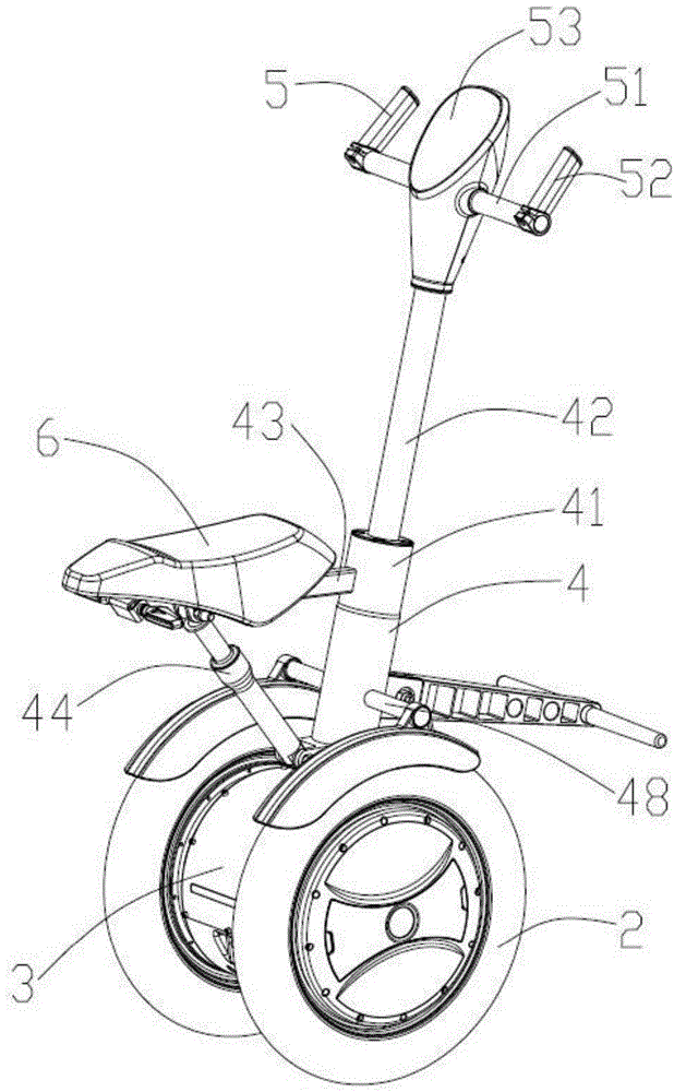
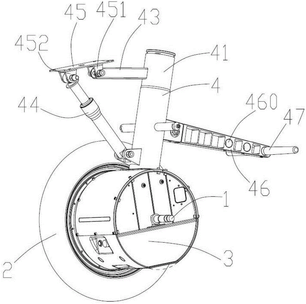
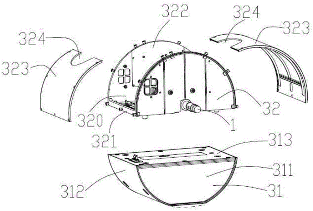
[0034] see figure 1 and figure 2 As shown, the electric balance vehicle of the present invention includes two wheels 2 mounted on the wheel shaft 1, a housing body 3 located between the two wheels 2, a bracket 4 fixedly connected to the wheel shaft 1, and a handle portion mounted on the bracket 4 5 and seat body 6.
[0035] The bracket 4 includes a first cylinder 41 connected to the wheel shaft 1, a second cylinder 42 mounted on the first cylinder 41 along the extending direction of the first cylinder 41, a fixing rod fixed on the first cylinder 41 The rod 43 , the supporting body 44 and the supporting body 45 rotatably connected to the first cylinder 41 . The seat body 6 is installed on the support body 45 . The fixing rod 43 , the supporting body 44 and the first cylinder 41 are roughly arranged in a triangular shape, so that the three have better stability when they are relatively stationary.
[0036] The support body 45 is provided with a first rotary connection part ...
Embodiment 2
[0051] Figure 9 The second embodiment of the electric balance vehicle of the present invention is shown. The difference between the second embodiment and the first embodiment lies in the fixing structure of the baffle plate 49 and the second footrests 9 provided on both sides of the wheel 2 .
[0052] The second pedal member 9 includes a post 91 mounted on the wheel axle and a pedal portion 92 rotatably mounted on the post 91 .
[0053] In this embodiment, in addition to being fixed by the cross bar 48, the baffle 49 is further provided with an outer fixing part 491, one end of the outer fixing part 491 is fixedly connected with the column 91, and the other end is located at the lower edge of the outer side of the wheel with the baffle 49. fixed connection. Further, an inner fixing part 492 may also be provided, one end of the inner fixing part 492 is fixedly connected to the accommodating body 3 , and the other end is fixedly connected to the lower edge of the baffle plate...
Embodiment 3
[0056] Figure 10 to Figure 12 The third embodiment of the electric balance car of the present invention is shown. The main difference between the third embodiment and the second embodiment is that a support rod 100 is installed on the front side of the first column 41 .
[0057] The support rod 100 is installed on the first column 41 through the fixing seat 200 . The fixing seat 200 includes a bottom 201 fixedly connected with the first cylinder 41 , a first lug 202 and a second lug 203 extending from the bottom 201 . The first lug 202 defines an arc-shaped through slot 2021 and a first shaft hole 2022 . The second lug 203 defines a second shaft hole 2032 , a first positioning hole 2031 and a second positioning hole 2033 . The first shaft hole 2022 is opposite to the second shaft hole 2032 for installing a rotating shaft 300 . The first positioning hole 2031 and the second positioning hole 2033 correspond to two ends of the arc-shaped through slot 2021 respectively.
[0...
PUM
 Abstract
Description
Claims
Application Information
 - R&D
- Intellectual Property
- Life Sciences
- Materials
- Tech Scout
- Unparalleled Data Quality
- Higher Quality Content
- 60% Fewer Hallucinations
Browse by: Latest US Patents, China's latest patents, Technical Efficacy Thesaurus, Application Domain, Technology Topic, Popular Technical Reports.
© 2025 PatSnap. All rights reserved.Legal|Privacy policy|Modern Slavery Act Transparency Statement|Sitemap|About US| Contact US: help@patsnap.com