Eureka AIR delivers breakthrough ideas for toughest innovation challenges, trusted by R&D personnel around the world.

High-stability scissor type aerial work platform

A high-altitude work platform, high-stability technology, applied in the direction of lifting devices, etc., can solve the problems of the negative impact of tire walking passability, the increase of equipment costs, and the heavy weight of lifting devices, so as to improve the efficiency and safety of equipment and ensure stability. sex, the effect of improving passability

Inactive Publication Date: 2015-08-12
ZHEJIANG DINGLI MACHINERY CO LTD
View PDF13 Cites 1 Cited by
  • Summary
  • Abstract
  • Description
  • Claims
  • Application Information

AI Technical Summary

Problems solved by technology

Due to the increasing working height of the existing aerial work platforms, the weight of the lifting device is also increasing, resulting in the lifting cylinder needing to withstand greater working pressure. In order to ensure the stability of the work, it is necessary to set up an auxiliary lifting cylinder. Auxiliary support, resulting in higher equipment costs
[0004] In order to ensure the stability of the platform when working at heights, it is necessary to provide more stable support for the work platform through the outrigger structure. However, the installation of the existing outrigger structure is relatively complicated, resulting in low assembly efficiency and resulting in maintenance. The process of removing the outriggers is more complicated
[0005] The existing structure of the aerial work platform usually installs support plates on both sides of the base to achieve the stability of high-altitude operations, which can play a supporting role in the process of tire height imbalance. It is a fixed installation structure, and the support plate will have a certain negative impact on the walking performance of the tire

Method used


Image

  • High-stability scissor type aerial work platform
  • High-stability scissor type aerial work platform
  • High-stability scissor type aerial work platform

Examples


Embodiment Construction

[0032] The present invention will be further described in detail below in conjunction with the accompanying drawings and examples. The following examples are explanations of the present invention and the present invention is not limited to the following examples.

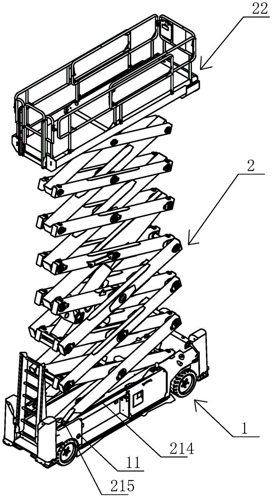
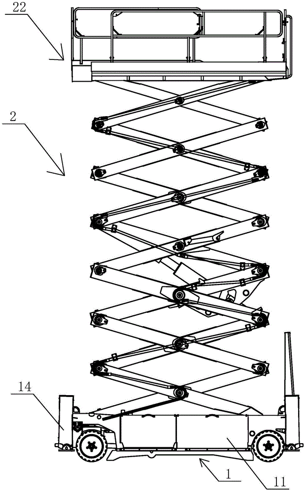
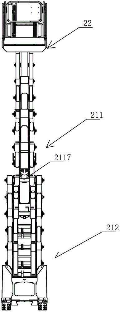
[0033] see Figure 1-Figure 18 In this embodiment, an aerial work platform includes a traveling chassis 1 and a lifting device 2. The traveling chassis 1 includes a chassis 11, a traveling device 12, a pothole protection mechanism 13 and an outrigger structure 14. The traveling device 12 includes a left Steering wheel 121, right steering wheel 122, left wheel frame 123, right wheel frame 124, linkage frame 125, steering oil cylinder 126 and turning to bent plate 127, described left steering wheel 121, right steering wheel 122 are respectively rotated and installed in left wheel frame 123, On the right wheel frame 124, the left steering wheel 121 and the right steering wheel 122 are respectively driven by the left dr...


PUM


Abstract

The invention relates to a high-stability scissor type aerial work platform which comprises a driving chassis and a lifting device. The driving chassis comprises a chassis body, a driving device, a pithole protection mechanism and landing leg structures; the lifting device comprises a scissor type lifting structure and a working platform, and the scissor type lifting structure comprises an upper scissor unit, a lower scissor unit and a lifting oil cylinder; the pithole protection mechanism comprises a left pithole plate, a right pithole plate, two first pithole connecting plates, two second pithhole connecting plates, two third pithole connecting plates, a fourth pithole connecting plate, two movable seats, two guide shafts, two limit plates and two movable seat pressure springs; each landing leg structure comprises a frame plate, a landing leg base plate, a landing leg mounting plate, an outer support pipe, an inner support pipe and a supporting foot. According to the high-stability scissor type aerial work platform, the weight of the lifting device is light, the work pressure born by the lifting oil cylinder is small, the stability of the driving and steering process is improved, and the landing leg structures are easy to mount and assemble.

Description

technical field [0001] The invention relates to a high-stability scissor type aerial work platform. Background technique [0002] Aerial work platform (Aerial work platform) is a product that serves mobile high-altitude operations such as aerial work, equipment installation, and maintenance in various industries. The related products of aerial work platforms mainly include: scissor-type aerial work platforms, vehicle-mounted aerial work platforms, articulating-arm aerial work platforms, self-propelled aerial work platforms, aluminum alloy aerial work platforms, and cylinder-type aerial work platforms. At present, there are mainly defects in the following aspects of aerial work platforms: [0003] The scissor lifting device is assembled by superimposing the scissor tubes that are cross-hinged with each other layer by layer. The scissor tubes on the bottom layer are hinged on the track wheels, and the track wheels can be moved on the chassis along the track. Slide back to ma...

Claims


Application Information

Patent Timeline
IPC IPC(8): B66F11/04
CPCB66F11/042
Inventor 许树根
Owner ZHEJIANG DINGLI MACHINERY CO LTD
Why Eureka
Eureka Blog
Learn More