
Folding door with linkage folding mechanism

A folding mechanism and folding door technology, applied in the field of folding doors, can solve the problems of reducing the overall feeling of the product and affecting the user experience, and achieve the effects of simple and reasonable structure, easy processing, and easy assembly and adjustment.

Active Publication Date: 2015-08-12
佛山市圣田智能科技有限公司
View PDF8 Cites 13 Cited by
  • Summary
  • Abstract
  • Description
  • Claims
  • Application Information

AI Technical Summary

Problems solved by technology

However, in order to realize the smooth linkage of the swing rod device, it must occupy the space other than the door leaf, which affects the user experience and reduces the overall sense of the product.

Method used


Image

  • Folding door with linkage folding mechanism
  • Folding door with linkage folding mechanism
  • Folding door with linkage folding mechanism

Examples


Embodiment 1

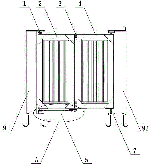
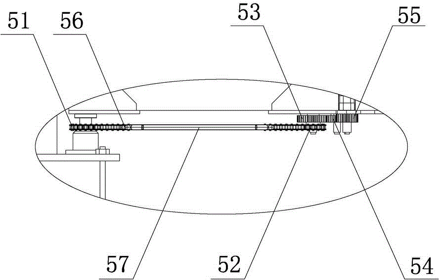
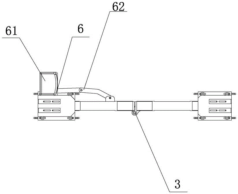
[0024] Such as Figure 1~6 As shown, a folding door with a linkage folding mechanism includes a group of folding door movable units, as well as a main doorpost 91 and a secondary doorpost 92. The movable unit includes a door shaft 1, an active door leaf 2, a coupling shaft 3, a slave Driven door leaf 4, linkage mechanism 5, driving mechanism 6, one end of the active door leaf 2 is hinged with the door shaft 1, and the other end is hinged with the driven door leaf 4 through the coupling shaft 3, and the linkage mechanism 5 includes a first sprocket 51, The second sprocket 52, the chain 56, the driving wheel 53, the transmission wheel group 54 and the driven wheel 55, the first sprocket 51 is fixedly connected with the door shaft 1 coaxially, and the second sprocket 52 and the driving wheel 53 are The active door leaf 2 is arranged coaxially close to the coupling shaft 3, the driven wheel 55 is coaxially fixedly connected with the coupling shaft 3, and the first sprocket 51 and ...

Embodiment 2

[0026] Such as Figure 7 As shown, its working principle is the same as that of Embodiment 1, the difference is that the movable unit of the folding door is provided with two groups, correspondingly, two gateposts 93 are also provided, each group of movable units corresponds to one gatepost 93 and Connected by the door shaft 1 , the self-locking clip 7 is arranged at the midpoint of the line connecting the two door posts 93 .


PUM


Abstract

The invention discloses a folding door with a linkage folding mechanism. The folding door comprises at least one movable unit. Each movable unit comprises a door shaft, a driving door leaf, a connecting shaft, a driven door leaf and a linkage mechanism, one end of each driving door leaf is hinged to the corresponding door shaft, the other end of each connecting shaft is hinged to the corresponding driven door leaf, each linkage mechanism comprises a first chain wheel, a second chain wheel, a chain, a driving wheel, a transmission wheel set and a driven wheel, each first chain wheel is fixedly and coaxially connected with the corresponding door shaft, each second chain wheel and the corresponding driving wheel are coaxially arranged at the portion, close to the corresponding connecting shaft, of the corresponding driven door leaf, each first chain wheel and the corresponding second chain wheel are connected in a fastened mode through the corresponding closed chain, each driven wheel and the corresponding connecting shaft are coaxially and fixedly connected, each transmission wheel set comprises multiple straight gears meshed with the corresponding driving wheel and the corresponding driven wheel. Due to the fact that power is transmitted through chain wheel sets of the chain wheel mechanisms, the chain wheels can be directly attached to the upper sides or the lower sides of the driving door leaf, and the folding door has the advantages of being attractive, elegant, strong in associative perception, simple and reasonable in structure, capable of easily machining parts and accessories and the like.

Description

technical field [0001] The invention relates to the technical field of folding doors, in particular to a folding door with a linkage folding mechanism. Background technique [0002] Because folding doors have the advantages of convenient use, space saving, and elegant appearance, they are widely used in workshops, shopping malls, office buildings, exhibition halls, and home decorations. Common movable units of folding doors include active door leaf, driven door leaf and linkage mechanism. Common linkage mechanisms are connecting rods or gears, such as the Chinese patent "Electric Folding Side Hinged Door" (notification number CN 103806828A), the active door leaf drives the driven door leaf to open and close through the swing rod device. However, in order to realize the smooth linkage of the swing rod device, it must occupy the space other than the door leaf, which affects the user experience and reduces the overall sense of the product. Contents of the invention [0003]...

Claims


Application Information

Patent Timeline
IPC IPC(8): E06B11/02E05F17/00E05F15/60
Inventor 周仲辉
Owner 佛山市圣田智能科技有限公司
Learn More