Wind electricity tower tube support frame

A technology of wind power tower and support frame, applied in the field of mechanical parts, can solve problems such as contact, and achieve the effect of convenient disassembly and assembly and good supporting effect

Inactive Publication Date: 2015-08-12
HUADIAN HEAVY MACHINERY
View PDF4 Cites 7 Cited by
  • Summary
  • Abstract
  • Description
  • Claims
  • Application Information

AI Technical Summary

Problems solved by technology

However, limited by its arc-shaped frame, it can only be used for wind power towers with similar sizes. For wind power tower

Method used


Image

  • Wind electricity tower tube support frame
  • Wind electricity tower tube support frame

Examples


Embodiment 1

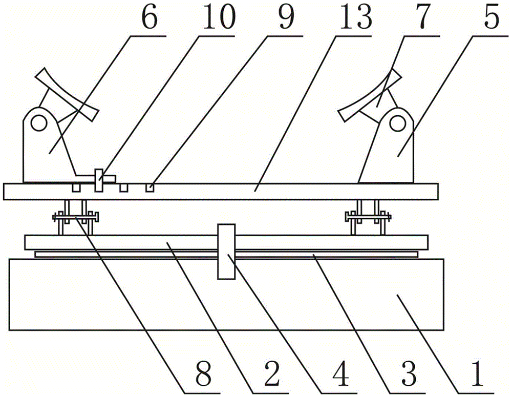
[0016] Such as figure 1 As shown, the turntable 2 is connected to the base 1 through the rotating shaft 4, the gasket 3 is located on the base 1 and the turntable 2, the support stand 13 is connected to the turntable 2 through a movable hinge 8, and the support stand 13 is provided with a fixed support frame 5 and The movable support frame 6, the fixed support frame 5 and the movable support frame 6 are respectively provided with an arc support plate 7, and the arc support plate 7 is movably connected with the fixed support frame 5 and the movable support frame 6 through pin shafts, and the fixed support frame 5 is fixed. On the support platform 13, the bottom of the movable support frame 6 is provided with a protrusion, and the protrusion is provided with a through hole. The support platform 13 is provided with a number of pin holes 9, and the movable support frame 6 is connected with the support platform 13 by a pin shaft 10. The shaft 10 passes through the through hole and ...

Embodiment 2

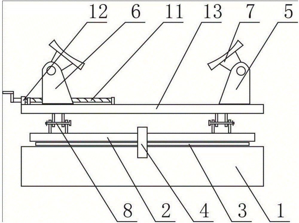
[0019] Such as figure 2 As shown, the turntable 2 is connected to the base 1 through the rotating shaft 4, the gasket 3 is located on the base 1 and the turntable 2, the support stand 13 is connected to the turntable 2 through a movable hinge 8, and the support stand 13 is provided with a fixed support frame 5 and The movable support frame 6, the fixed support frame 5 and the movable support frame 6 are respectively provided with an arc support plate 7, and the arc support plate 7 is movably connected with the fixed support frame 5 and the movable support frame 6 through pin shafts, and the fixed support frame 5 is fixed. On the support platform 13 , a lead screw 11 is arranged on the support platform 13 , the movable support frame 6 is located on the lead screw 11 , and the lead screw 11 is equipped with a locking mechanism 12 .

[0020] When in use, select a suitable arc-shaped support plate 7 according to the size of the wind power tower, and then use the locking device 12...


PUM


Abstract

The invention provides a wind electricity tower tube support frame, and belongs to a mechanical component. The wind electricity tower tube support frame comprises a base, a rotating table, a gasket, a rotating shaft and a support table, wherein the rotating table is connected with the base through the rotating shaft; the gasket is positioned on the base and the rotating table; the support table is connected with the rotating table through a movable hinge. The wind electricity tower tube support frame is characterized in that a fixed support frame and a movable support frame are arranged on the support table; an arc-shaped support plate is respectively arranged on the fixed support frame and the movable support frame. The distance between the two support frames can be adjusted by the movable support frame; for wind electricity tower tubes in different sizes, the arc-shaped support frame can be well in contact with the outer walls of the wind electricity tower tubes, a good support effect is achieved, and the abrasion of the outer walls of the wind electricity tower tubes cannot be caused. The arc-shaped support plates and the support frames are connected through pin shafts, the dismounting and the mounting are convenient, and the arc-shaped support plates with proper radians can be replaced according to the sizes of the wind electricity tower tubes.

Description

technical field [0001] The invention belongs to mechanical components, in particular to a wind power tower support frame. Background technique [0002] The wind power tower is the tower pole of wind power generation, which mainly plays a supporting role in the wind power generation unit. Wind power towers are bulky and heavy, making transportation very inconvenient. In order to facilitate transportation, the support platform of the wind power tower is generally rotatable to facilitate its lateral rotation. But one end of the tower tube is placed behind the support platform, and the up and down movement of the other end will cause the contact area between the tower tube and the support platform to become smaller, and the local force will be too large, which will easily cause wear and tear of the tower tube and damage the support platform. The Chinese patent with the authorized notification number CN203856653U discloses a rotary support platform for wind power towers, includ...

Claims


Application Information

Patent Timeline
IPC IPC(8): F03D11/04
Inventor 侯艳华胡建新
Owner HUADIAN HEAVY MACHINERY
Why Eureka
Try Eureka