LED lamp and LED light source module

A technology of LED light source and LED lamp, which is applied in the direction of light source, electric light source, point light source, etc., can solve the problems of rising cost of the whole lamp, unable to realize standardized design of radiator, etc., and achieve the effect of reducing volume

Inactive Publication Date: 2015-08-12
OPPLE LIGHTING
View PDF7 Cites 1 Cited by
  • Summary
  • Abstract
  • Description
  • Claims
  • Application Information

AI Technical Summary

Problems solved by technology

The lamp shell is limited by appearance, installation size, optical performance and safety regulations. It is difficult to make an optimal design only according to the heat dissipation requirements, and it is also impossible to realize the standardized design of the radiator, which leads to an increase in the cost of the whole lamp.

Method used


Image

  • LED lamp and LED light source module
  • LED lamp and LED light source module
  • LED lamp and LED light source module

Examples


Embodiment Construction

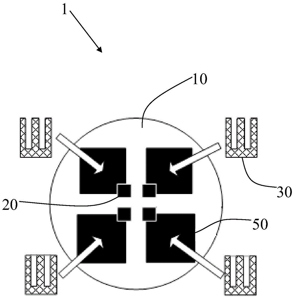
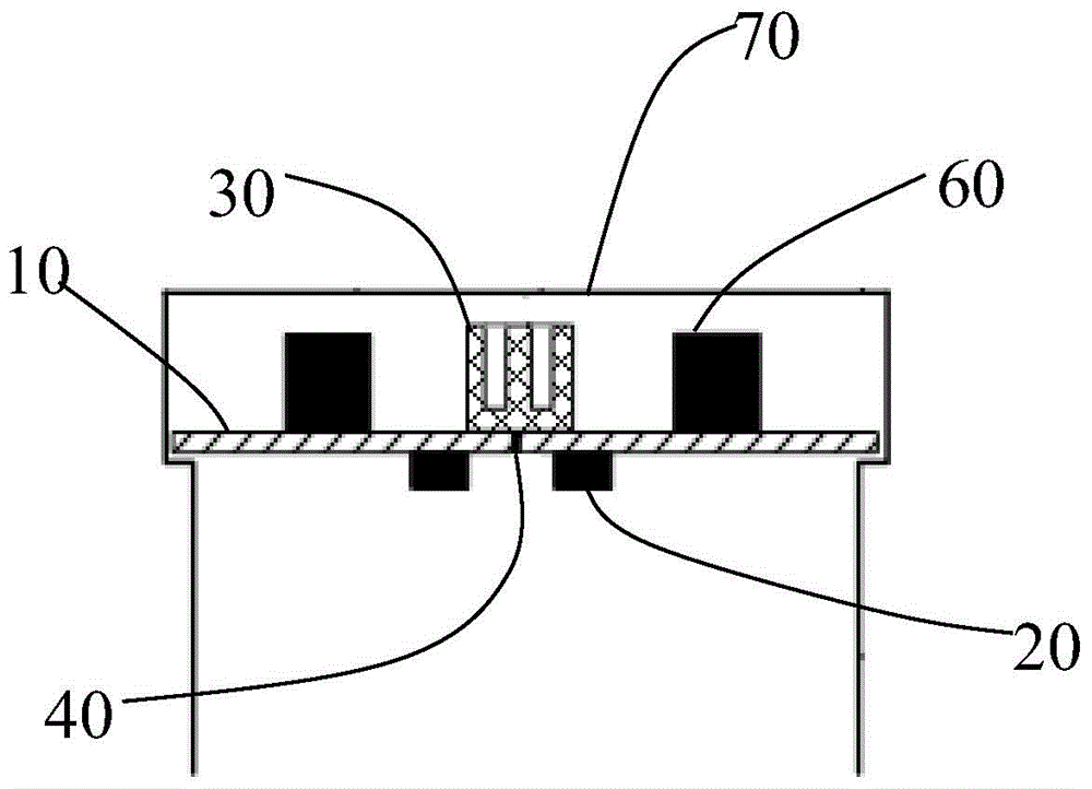
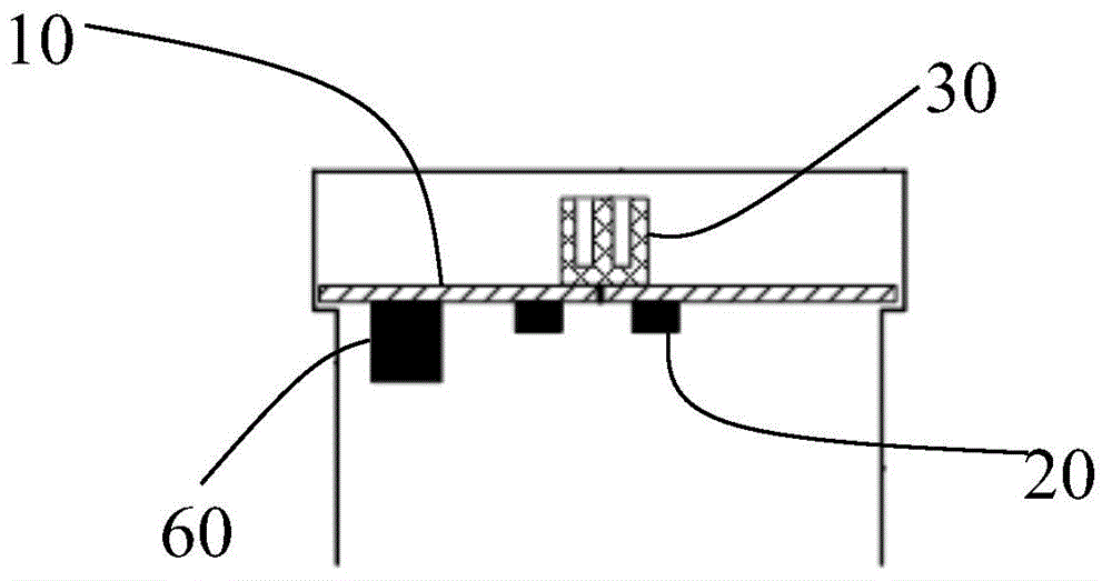
[0033] Please refer to figure 1 As shown, an LED lamp 1 according to the first preferred embodiment of the present invention includes a light source board 10, a number of LED particles 20 mounted on the light source board 10, and a number of heat sinks 30. Each two LED particles 20 correspond to one or more There are two heat sinks 30, and heat conduction is formed between each LED particle 20 and its corresponding heat sink 30. In the present invention, one or more heat sinks 30 are provided for every two LED particles 20, and the heat sinks 30 are dispersed and distributed on each LED particle 20 instead of being a large whole, so that the internal space of the LED lamp 1 can be configured conveniently and flexibly. Reserving a large space for the radiator 30 can effectively reduce the volume of the LED lamp 1 and make the overall shape design of the LED lamp 1 flexible.

[0034] Every two LED particles 20 corresponds to a heat sink 30 or each LED particle 20 corresponds to a h...


PUM


Abstract

The invention discloses an LED lamp and an LED light source module. The LED lamp comprises a light source plate, multiple LED particles installed on the light source plate and multiple radiators. Every two LED particles correspond to one or more radiators, and heat transfer is formed between each LED particle and the corresponding radiator.

Description

【Technical Field】 [0001] The invention relates to a lighting device, in particular to an LED lamp and an LED light source module. 【Background technique】 [0002] In modern lighting devices, more and more LED light sources replace traditional light sources. If the heat of the LED light source is too high, the life of the LED light source will be shortened, and the performance will deteriorate. Therefore, a heat sink is usually used in LED lamps to help the LED light source dissipate heat. In the prior art, the entire lamp structure usually uses a metal lamp body shell as a heat sink. The lamp housing is restricted by various aspects such as appearance, installation size, optical performance, and safety regulations. It is difficult to make the optimal design only according to the heat dissipation requirements, and it is impossible to realize the standardized design of the radiator, which leads to the increase of the cost of the whole lamp. [0003] Therefore, in order to overcome ...

Claims


Application Information

Patent Timeline
Patent Type & Authority Applications(China)
IPC IPC(8): F21S2/00F21V29/503F21V29/76F21Y101/02
Inventor 左壮余世伟
Owner OPPLE LIGHTING
Why Eureka
Try Eureka