Electric wire clamp

A wire and wire technology, applied to the field of special tooling for wire harness production, can solve the problems of inconvenient adjustment of clamping size, easy damage to wires, unstable clamping, etc. Fast and stable clamping effect

Active Publication Date: 2015-08-12
杨志强
View PDF5 Cites 8 Cited by
  • Summary
  • Abstract
  • Description
  • Claims
  • Application Information

AI Technical Summary

Problems solved by technology

However, since this type of wire clamp has fewer clamping points for the wire, in order to achieve a stable clamping of the wire, a large pre-tightening force is often required. Under the action of a large clamping force, the wire will be deformed Even if the wire is damaged, etc.
For the optimization of the second type of wire clamp, three-point or four-point clamping wire clamps have also appeared in the traditional technology. However, due to the optimized wire clamp, due to the softness of the outer insulating layer of the wire, each clamping part is far from the wire. The distance from the central axis is not equal
As a result, the clamping force exerted by different c

Method used


Image

  • Electric wire clamp
  • Electric wire clamp
  • Electric wire clamp

Examples


Embodiment Construction

[0024] The present invention will be further explained below in conjunction with the accompanying drawings and specific embodiments.

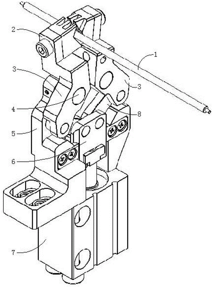
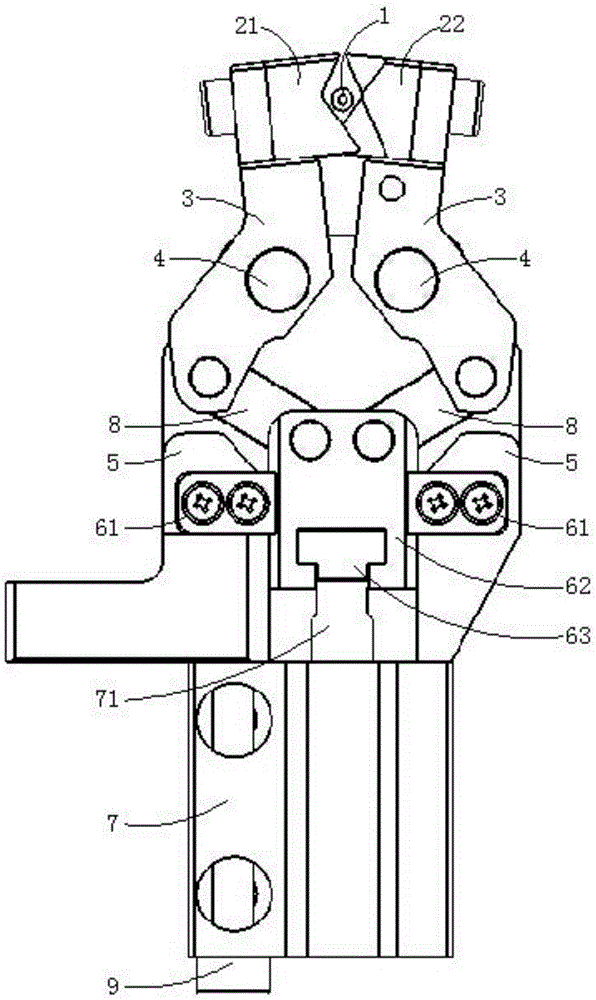
[0025] Such as Figure 1 to Figure 5 As shown, the wire clamp of this embodiment includes a clamping mechanism 2 composed of a left clamping part 21 and a right clamping part 22, two symmetrically arranged rotating rods 3, a base 5, a cylinder 7 and two connecting rods 8 .

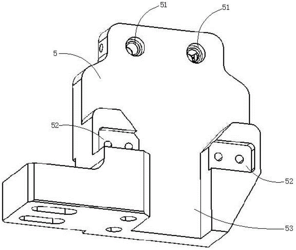
[0026] The lower end of base 5 is provided with transmission block chute 53, and the base 5 above transmission block chute 53 is provided with two bearing pins-mounting hole 51, and the groove wall of transmission block chute 53 left and right sides is respectively fixedly provided with limit position. Block 61. The lower end of the base 5 is fixedly connected with the cylinder 7 through a fixing bolt 9 .

[0027] The middle parts of the two rotating rods 3 are respectively hinged with the base 5 through a pin shaft-4, and the two pin shafts-4 are installed in the two pi...


PUM


Abstract

The invention belongs to the wire harness making special-purpose tool field, and specifically provides an electric wire clamp comprising a cylinder and a transmission mechanism directly connected with a cylinder piston; the cylinder is used for controlling a left clamp portion and a right clamp portion to open and close; clamp portions of the left and right clamp portions respectively comprise a plurality of clamp convex teeth and clamp grooves mutually matched. The beneficial effects are that the single cylinder can automatically control the clamp portions to open and close, so the electric wire clamp can be applied to wire harness making automation production; the opening size of the electric wire clamp is adjustable, so electric wires of different diameters can be clamped; electric wire clamping force is uniformly distributed, so the electric wire cannot be damaged in a clamp process; clamping is stable, convenient and fast; parts assembling and dismounting are convenient and fast; the electric wire clamp is concise in structure, low in production processing difficulty, and high in clamp workpiece stability.

Description

technical field [0001] The invention belongs to the field of special tooling for wire harness production, and in particular relates to a wire clip. Background technique [0002] The wires mentioned herein generally refer to all linear objects that can be made into wire harnesses, such as electric wires, optical fibers, and cables, optical cables, etc., respectively or separately composed of the two. [0003] The current wire clamp tooling is mainly divided into two types. The main structure of the first kind of wire clip is two half circles, and the two half circles clamp the electric wire in an arc shape. This kind of electric wire has a better clamping effect, and the clamping force is evenly distributed, which is not easy to cause damage to the electric wire. For example, the notification number is CN104577935A Chinese Invention Patent which discloses the structure of a C-shaped clamp. However, this type of clamp has problems such as inability to clamp wires of differe...

Claims


Application Information

Patent Timeline
IPC IPC(8): H01B13/012G02B6/44
Inventor 杨志强
Owner 杨志强
Why Eureka
Try Eureka