Charge and discharge control circuit

A charging and discharging control and charging circuit technology, which is applied in the direction of battery circuit devices, circuit devices, collectors, etc., can solve the problem of increasing fault points, achieve the effect of reducing power consumption, solving the problem of increasing fault points, and reducing hardware fault points

Active Publication Date: 2017-11-03
BEIQI FOTON MOTOR CO LTD
View PDF4 Cites 0 Cited by
  • Summary
  • Abstract
  • Description
  • Claims
  • Application Information

AI Technical Summary

Problems solved by technology

[0005] The embodiment of the present invention provides a charging and discharging control circuit to at least solve the technical problem that the hardware redundancy design of the existing charging and discharging control circuit leads to an increase in failure points

Method used


Image

  • Charge and discharge control circuit
  • Charge and discharge control circuit
  • Charge and discharge control circuit

Examples


Embodiment 1

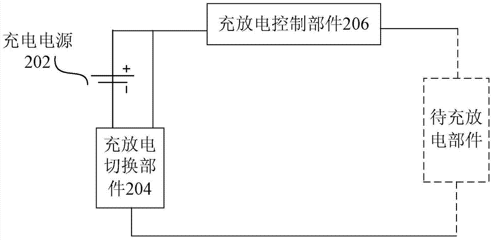
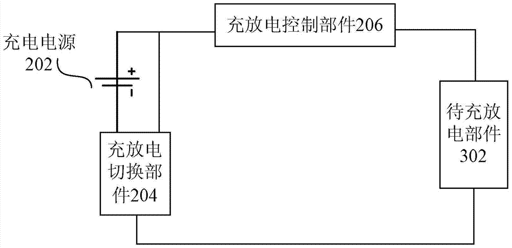
[0025] According to an embodiment of the present invention, a charging and discharging control circuit is provided, such as figure 2 As shown, the circuit includes:

[0026] 1) Charging power supply 202;

[0027] 2) The charging and discharging switching part 204, wherein, when the charging and discharging switching part 204 is in the first connection state, at least the charging power supply 202, the charging and discharging control part 206 and the parts to be charged and discharged constitute a charging circuit for charging the parts to be charged and discharged , when the charging and discharging switching component 204 is in the second connection state, at least the charging and discharging control component 206 and the component to be charged and discharged constitute a discharge circuit for discharging the component to be charged and discharged;

[0028] 3) The charge and discharge control part 206 is used to connect the charge and discharge load to the charging circu...


PUM


Abstract

The invention discloses a charging and discharging control circuit, wherein the circuit includes: a charging power supply; The discharging component constitutes a charging circuit for charging the component to be charged and discharged, and when the charging and discharging switching component is in the second connection state, at least the charging and discharging control component and the component to be charged and discharged constitute a discharging circuit for discharging the component to be charged and discharged; The charging and discharging control part is used for connecting the charging and discharging load into the charging circuit when charging the charging and discharging parts, and connecting the charging and discharging load into the discharging circuit when discharging the charging and discharging parts. The invention solves the technical problem that the hardware redundancy design of the existing charging and discharging control circuit leads to the increase of failure points.

Description

technical field [0001] The invention relates to the field of electric vehicles, in particular to a charging and discharging control circuit. Background technique [0002] At present, the existing electric vehicle system includes multiple high-voltage system loads such as the motor system. Therefore, a pre-charging circuit is provided in the high-voltage circuit to reduce the current impact when the system is powered on; at the same time, a discharge circuit is also provided to realize After the whole vehicle is powered off, the electric energy and voltage stored in the high-voltage system are discharged to a safe voltage. Nowadays, circuit designs commonly used in this field such as figure 1 Shown: 1) There is a pre-charging contactor K3 and an independent pre-charging resistor R1 in the power-on pre-charging circuit; 2) There is an independent discharging contactor K5 and a discharging resistor R2 in the discharging circuit, and the discharging contactor K5 is Normally cl...

Claims


Application Information

Patent Timeline
Patent Type & Authority Patents(China)
IPC IPC(8): H02J7/00
Inventor 卫晓薇
Owner BEIQI FOTON MOTOR CO LTD
Why Eureka
Try Eureka