Supercharge Your Innovation With Domain-Expert AI Agents!

Float glass production device and float glass production method

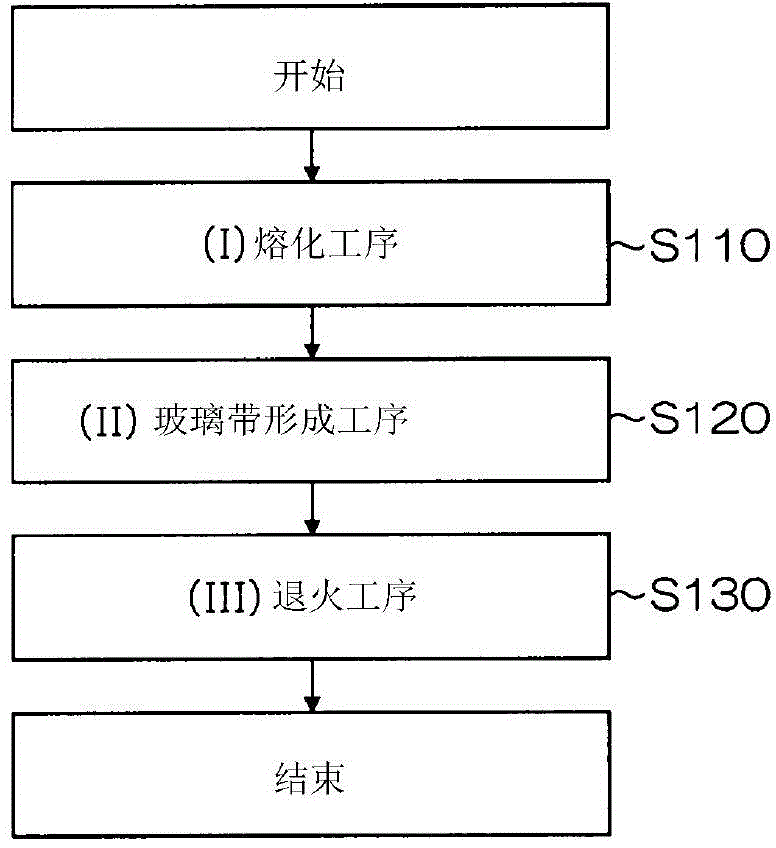
A technology for float glass and manufacturing equipment, which is applied in the field of float glass manufacturing equipment, which can solve the problems of difficulty in manufacturing thickness, high adhesion between tin and the surface of the upper roll, and loss of productivity, and achieve the effect of suppressing plate width fluctuations

Inactive Publication Date: 2015-08-12
ASAHI GLASS CO LTD
View PDF8 Cites 2 Cited by
  • Summary
  • Abstract
  • Description
  • Claims
  • Application Information

AI Technical Summary

Problems solved by technology

If the tin attached to the contact portion of the upper roll between the upper roll and the glass ribbon increases, under the influence of the thickness of the tin, there will be fluctuations in the pressure that the upper roll presses the glass ribbon, and the tin will easily adhere to the glass ribbon. Top, glass ribbon and top roll become difficult to separate
Therefore, there is a problem that the thickness of the glass ribbon fluctuates and it is difficult to manufacture flat glass with uniform thickness.
[0010] In order to prevent the increase of the attached tin, although it is also possible to intermittently vibrate the upper roll and send inert gas to the upper roll, if the adhesion between tin and the surface of the upper roll is high, no sufficient effect can be obtained
In addition, there is also a problem that since the adhesion between tin and the upper roll becomes stronger over time, the upper roll needs to be replaced at regular intervals, which impairs productivity.

Method used


Image

  • Float glass production device and float glass production method
  • Float glass production device and float glass production method
  • Float glass production device and float glass production method

Examples


Embodiment

[0105] An example at the time of manufacturing the alkali-free glass (AN100: Asahi Glass brand name) whose size is 2500 mm x 2200 mm x 0.7 mm is shown below.

[0106] Figure 6 It is a graph showing the diurnal fluctuations of the cooling water temperature Tb and the outside air temperature Ta under the above conditions. The vertical axis of the graph represents the cooling water temperature Tb and the outside air temperature Ta. The solid line represents the cooling water temperature. The outside air temperature is indicated by a dotted line, and the value of the outside air temperature is measured by a temperature measuring device installed in the float tank building. In addition, the amount of variation on the vertical axis is normalized by setting the respective minimum temperatures to 0°C. Let the normalized cooling water temperature Tb and the outside air temperature Ta be Tb' and Ta', respectively.

[0107] according to Figure 6 , although the external air tempera...


PUM


Abstract

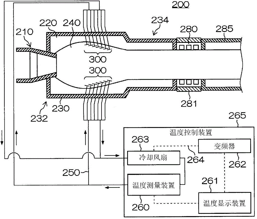
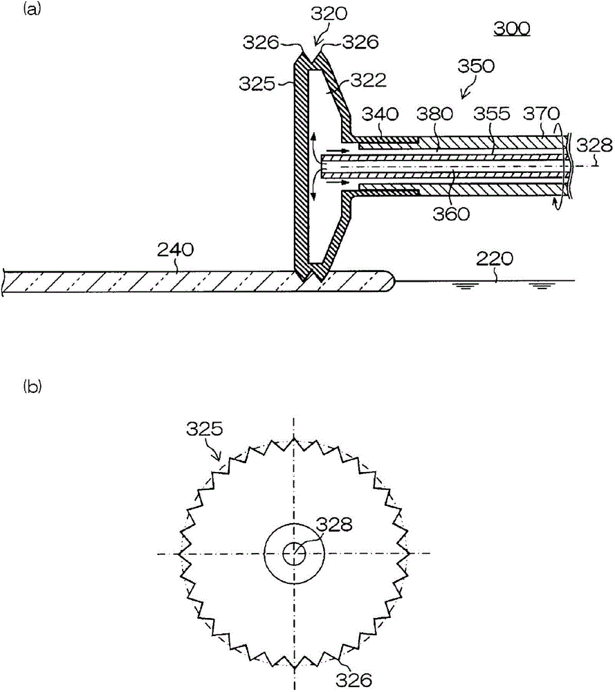
The present invention provides a float glass production device and a float glass production method that suppress the dropping of tin fixed to a top roll surface on to a glass ribbon or inside a molten tin bath during production, and suppress variation in glass ribbon plate thickness. The present invention pertains to a float glass production device comprising a float bath (230) wherein a molten glass ribbon (240) is carried, and a top roll (300) used to suppress the expansion / contraction of the molten glass ribbon (240). The float glass production device (200) is characterized by: the top roll (300) having a rotatable tip section (320) that comes in contact with the molten glass ribbon (240); the tip section (320) having a hollow structure having an internal tip section space (322), and having a flow channel that provides cooling water to the tip section space (322); and the fluctuation margin for the cooling water temperature being controlled to within 4°C per day, by a temperature control device (265) comprising a temperature measurement device that measures the cooling water temperature and is arranged on the outside of the float bath, and a cooling device that cools the cooling water having had the temperature thereof increased by heat exchange inside the float bath.

Description

technical field [0001] The present invention relates to a float glass manufacturing device and a float glass manufacturing method. Background technique [0002] As one method of manufacturing a glass plate, the float method is known. In this float method, sheet glass is manufactured roughly through the following steps. [0003] (1) Molten glass is introduced onto the surface of molten tin accommodated in the float bath. [0004] (2) The molten glass is continuously fed along the molten tin from the upstream side to the downstream side to form a glass ribbon. [0005] (3) Lightly press both ends of the glass ribbon to suppress shrinkage of the glass ribbon in the width direction. [0006] (4) While annealing the glass ribbon, the glass ribbon is pulled out from the float tank by roller conveyance, thereby manufacturing sheet glass. [0007] Here, in the process of (3), what is called a top roll is used. The upper rollers are provided in the upstream region of the float t...

Claims


Application Information

Patent Timeline
IPC IPC(8): C03B18/06
CPCC03B18/06
Inventor 田中誓也稻井要介
Owner ASAHI GLASS CO LTD
Features
  • R&D
  • Intellectual Property
  • Life Sciences
  • Materials
  • Tech Scout
  • Unparalleled Data Quality
  • Higher Quality Content
  • 60% Fewer Hallucinations
Learn More