A punching and bending die for highway l-shaped bolts

A bolt and L-shaped technology, applied in the field of metal stamping, can solve the problems of high process cost, inability to repair threads, and high production cost, and achieve the effects of simplifying manual operation steps, improving production efficiency, and high automation.

Active Publication Date: 2017-11-03
江苏新聚环保科技有限公司
View PDF6 Cites 0 Cited by
  • Summary
  • Abstract
  • Description
  • Claims
  • Application Information

AI Technical Summary

Problems solved by technology

The outer diameter of the thread rolling die must be more than Φ290 to process, but the Φ290 thread rolling die cannot be installed on the I28-60 thread rolling machine, and the special thread rolling machine and the thread rolling die must be customized, so the production cost is relatively high
Thread rolling is used for L bolts, but ordinary punching and bending dies cannot be completed. The threaded part of L bolts is too close to the R part. From the ordinary punching and bending process, it can be seen that its force is at the R part of the die during punching and bending. Product L can be seen after punching and bending 1 The defect that the threaded part is recessed is obvious
Therefore, the L bolt cannot reach the product standard after punching and rolling the thread with an ordinary punching die. After the thread is defective, due to the L bolt L 2 If the part is too long, the threads cannot be repaired on the thread rolling machine, and the thread rolling machine cannot roll over
If the thread is repaired by other methods, and the thread is repaired with a garden die, first, the thread can pass, but the outer diameter of the thread cannot be increased. Second, the tensile strength test is also affected by the defect of the outer thread.
3. The process cost of repairing the thread with a round die is several times higher, so it is not feasible to use an ordinary punching die to bend the L bolt after it has been rolled.

Method used


Image

  • A punching and bending die for highway l-shaped bolts
  • A punching and bending die for highway l-shaped bolts
  • A punching and bending die for highway l-shaped bolts

Examples


Embodiment Construction

[0027] The following are specific embodiments of the present invention and in conjunction with the accompanying drawings, the technical solutions of the present invention are further described, but the present invention is not limited to these embodiments.

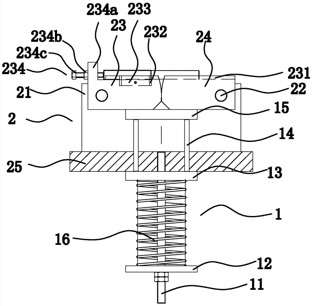
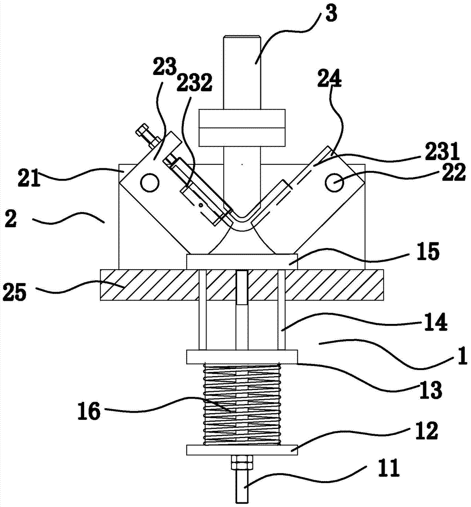
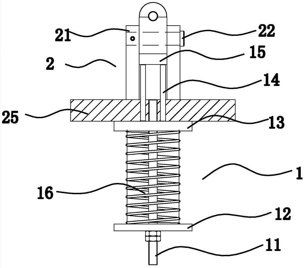
[0028] Such as figure 1 with image 3 As shown, the present invention includes a punch, a punch connected to the punch, a buffer 1 and a die assembly 2 installed on the buffer 1, the die assembly 2 includes a base plate 25, and the die assembly 2 installed side by side on the base plate 25 Bracket 21, pin shaft 22 passing through bracket 21 and dies sleeved on the pin shaft 22 respectively, the die is located between brackets 21, buffer 1 includes connecting rod 11, one end is installed on the bottom plate Connecting rod 11, the lower pad 12 installed on the other end of the connecting rod 11, the upper pad 13 sleeved on the connecting rod 11 and some pins 14, one end of the pin 14 passes through the bottom plate 25 to co...


PUM


Abstract

The invention provides a bending die for an L-shaped highway bolt, and belongs to the technical field of metal stamping. The problems that an existing L-shaped bolt bending die is high in cost, and thread protection is not in place are solved. The bending die for the L-shaped highway bolt comprises a buffer and a female die assembly installed on the buffer; the female die assembly comprises a base plate, a bracket installed on the base plate and female dies hinged to the bracket; the buffer comprises a top block which penetrates through the base plate to abut against the female dies, and the top surfaces of the female dies are provided with grooves; the female dies comprise a locating female die and a matching female die, and the end of the locating female die and the end of the matching female die are tangent and can rotate towards the center of the locating female die and the center of the matching female die. The bending die for the L-shaped highway bolt has the advantages that the production efficiency is high, the operation is easy and convenient, and one-time forming is achieved.

Description

technical field [0001] The invention belongs to the technical field of metal stamping, and relates to a punching die device for road L-bolts, in particular to a punching and bending die for road L-shaped bolts. Background technique [0002] L bolt is a non-standard part used in highway bridges. With the great development of national highway construction, the number of L bolts used has also increased sharply. However, because the stem of this kind of bolt is an L-shaped bend in space, According to the current equipment, it is not easy to guarantee the quality of the product. The main difficulty lies in the second process of punching and bending the product first or rolling the thread first. Looking at the product picture, it is more convenient to use ordinary bending dies to punch and bend first, but after bending, according to the characteristics of L bolts, it is impossible to roll L bolts on ordinary thread rolling machines. See the process diagram of the thread rolling ma...

Claims


Application Information

Patent Timeline
Patent Type & Authority Patents(China)
IPC IPC(8): B21D37/10B21D53/24
CPCB21D37/10B21D53/24
Inventor 蔡体勇王巍
Owner 江苏新聚环保科技有限公司
Why Eureka
Try Eureka